Please do not block ads on our site. Clicks on ads help us exist, grow and become more useful for you!
Calculation of Three-way control Valve
 EXAMPLE


There is a belief that the selection of a three-way valve does not require preliminary calculations. This assumption is based on the fact that the overall flow of water through the AB pipe does not depend on the position of the stem and always remains constant. In reality, the flow through the common AB pipe changes depending on the position of the stem, and the magnitude of the changes depends on the authority of the three-way valve and its regulating characteristics.
Methodology for Calculating Three-Way Valves
The calculation of a three-way valve is performed in the following sequence:
- 1. Selection of the optimal regulating characteristic.
- 2. Determination of the regulating capacity (authority) of the valve.
- 3. Determination of the flow capacity and nominal diameter.
- 4. Selection of the electric drive for the regulating valve.
- 5. Checking for noise and cavitation.
Selection of Regulating Characteristic
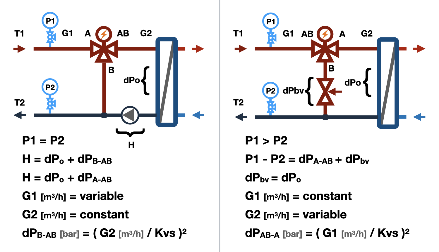
The dependence of water flow through the valve on the stem position is called the regulating characteristic. The type of regulating characteristic determines the shape of the valve disc and seat. Since a three-way valve has two discs and two seats, it also has two regulating characteristics, the first denoted by the characteristic for direct passage - (A-AB), and the second for perpendicular passage - (B-AB).
Linear/linear. The total flow of water through the AB pipe is constant only at a valve authority equal to 1, which is practically impossible to achieve. The operation of a three-way valve with an authority of 0.1 will result in fluctuations in the total flow when the stem is moved, in the range of 100% to 180%. Therefore, valves with a linear/linear characteristic are used in systems that are insensitive to fluctuations in water flow or in systems with a valve authority of no less than 0.8.
Logarithmic/logarithmic. Minimal fluctuations of the total water flow through the AB port in three-way valves with logarithmic/logarithmic regulating characteristics are observed at a valve authority of 0.2. Decreasing the authority compared to this value increases the total flow through the AB port, while increasing it decreases the total flow. The flow fluctuations in the authority range from 0.1 to 1 range from +15% to -55%.
Logarithmic/linear. Three-way valves with logarithmic/linear characteristics are used when different laws of regulation are required in circulation loops passing through the A-AB and B-AB ports. Flow stabilization during valve movement occurs at an authority of 0.4. Fluctuations of the total flow through the AB port in the authority range from 0.1 to 1 range from +50% to -30%. Regulating valves with logarithmic/linear characteristics have found wide application in control nodes of heating systems and heat exchangers.
Calculation of Authority
The authority of a three-way valve is equal to the ratio of the pressure drop across the valve to the sum of the pressure drops across the valve and the regulated section. The authority value for three-way valves determines the range of fluctuation of the total flow through the AB port.
A 10% deviation of the water flow through the AB port during stem movement is ensured at the following authority values:
- A+ = (0.8-1.0) - for valves with linear/linear characteristics.
- A+ = (0.3-0.5) - for valves with logarithmic/linear characteristics.
- A+ = (0.1-0.2) - for valves with logarithmic/logarithmic characteristics.
The authority for three-way valves is determined for each of the two circulation loops passing through the A-AB and B-AB ports.
After determining the optimal range of authorities and regulating characteristics, the allowable range of pressure drops across the three-way valve is determined, and then its flow capacity is determined.
Calculation of flow capacity
The dependence of pressure drops on the valve on the water flow through it is characterized by the coefficient of flow capacity Kvs. The value of Kvs is equal to the water flow rate in m³/h through a fully open valve, at which the pressure drop across the valve is 1 bar. Usually, the Kvs values of a three-way valve are the same for the A-AB and B-AB ports, but there are valves with different flow capacity values for each port.
Knowing that when the water flow changes by 'n' times, the pressure drops across the valve change by 'n²' times, it is easy to determine the necessary Kvs of the regulating valve by substituting the calculated flow rate and pressure drops into the equation. From the catalog, a three-way valve with the closest value of the flow capacity coefficient to the value obtained in the calculation is selected.
Selection of electric actuator
The electric actuator is selected for the previously selected three-way valve. It is recommended to choose electric actuators from the list of compatible devices specified in the valve characteristics, taking into account:
- The connection nodes of the actuator and the valve must be compatible.
- The stroke of the electric actuator rod should be no less than the stroke of the valve rod.
- Depending on the inertia of the controlled system, actuators with different speeds should be used.
- The maximum pressure drop across the valve, at which the actuator can close it, depends on the closing force of the actuator.
- The same electric actuator provides closure of the three-way valve, which operates on flow mixing and separation, at different pressure drops.
- The power supply voltage and the actuator control signal should correspond to the power supply voltage and the control signal of the controller.
- The rotary three-way valves must be operated only by electric actuators with a rotary motion.
Calculation of cavitation probability
Cavitation is the formation of vapor bubbles in a water flow, which occurs when the pressure in the flow drops below the saturation pressure of water vapor. The effect of increasing flow velocity and decreasing pressure in the flow, which occurs when the passage cross-section is narrowed, is described by Bernoulli's equation. The passage cross-section between the valve and the saddle of the three-way valve is such a narrowing, where the pressure can drop to the saturation pressure, and it is the most likely place for cavitation to occur. Vapor bubbles are unstable, they appear suddenly and collapse just as suddenly, which leads to the erosion of metal particles from the valve components, which inevitably leads to premature wear. In addition to wear, cavitation leads to increased noise during valve operation.
The main factors that affect cavitation:
- Water temperature - the higher it is, the more likely cavitation is to occur.
- Water pressure - before the regulating valve, the higher it is, the less likely cavitation is to occur.
- Allowable pressure drop - the higher it is, the higher the probability of cavitation.
- The cavitation characteristic of the three-way valve is determined by the features of the throttling element of the valve. The cavitation coefficient is different for different types of regulating valves and should be specified in their technical specifications, but since most manufacturers do not indicate this value, the calculation algorithm includes a range of the most likely cavitation coefficients.
As a result of checking for cavitation, the following result can be obtained:
- 'None' - cavitation will definitely not occur.
- 'Possible' - cavitation may occur on the valves of certain designs, it is recommended to change one of the aforementioned influencing factors.
- 'Yes' - cavitation will definitely occur, change one of the factors that influence the occurrence of cavitation.
Calculation for noise generation
The high velocity of the flow in the inlet of a three-way valve can cause high noise levels. For most premises in which regulating valves are installed, the permissible noise level is 35-40 dB (A), which corresponds to a velocity of approximately 3 m/s in the inlet of the valve. Therefore, when selecting a three-way valve, it is not recommended to exceed the aforementioned velocity.
question : comment : feedback
 Online Equipment calculations