Please do not block ads on our site. Clicks on ads help us exist, grow and become more useful for you!
Calculation of Control Valve
 EXAMPLE


Methodology for calculating the regulating valve
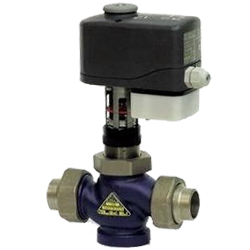
Dual-control valves in engineering systems have a multitude of applications, the most common of which is their use in conjunction with a controller and temperature sensors as a regulator for heating, ventilation or hot water supply systems.
Regardless of the task at hand, calculating the regulating valve involves determining its flow capacity, at which a given flow rate of the heat carrier will be throttled to the desired pressure. In addition to compliance with the flow capacity, the selected regulating valve should be checked for the possibility of cavitation and noise generation due to the high flow rate of water through it.
The regulating valve is necessary primarily for regulation, so it should be selected in such a way as to maximize the dependence of the controlled variable on the stroke of the stem, while taking into account the importance of parameters such as the regulating valve characteristic and the authority of the regulating valve.
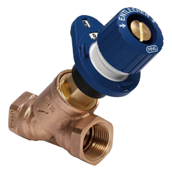
Calculating the flow capacity of the regulating valve
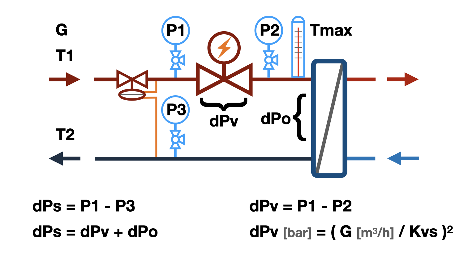
The dependence of pressure drop on flow rate through the regulating valve is called flow capacity - Kvs.
Kvs - flow capacity is numerically equal to the flow rate in m³/hour through a fully open regulating valve, at which the pressure drop on it is equal to 1 bar.
Kv - the same, for partial opening of the valve shutter.
Knowing that when costs change n times, the pressure drop across the valve changes n² times, it is easy to determine the necessary Kv of the regulating valve by substituting the calculated flow rate and excess pressure into the equation.
Some manufacturers recommend selecting a regulating valve with the nearest higher Kvs value than the obtained Kv value. This approach allows for more accurate regulation of the flow of the heat transfer fluid below the calculated value, but does not allow for increasing the flow rate of the heat transfer fluid above the set value, which is often necessary. We do not criticize the above-described method, but recommend selecting a two-way regulating valve in such a way that the required value of the flow capacity is in the range of 50 to 80% of the stroke length. A regulating valve designed in this way will be able to both decrease and slightly increase the flow rate with sufficient accuracy.
The described calculation algorithm outputs a list of regulating valves for which the required Kv value falls within the range of the stroke length from 50 to 80%.
The selection results show the percentage of the regulating valve shutter opening at which the excess pressure at the specified flow rate is throttled. The presented values of the opening percentage take into account the curvature of the regulating valve characteristic and its change due to the deviation of the authority from 1.
Selection of the regulating valve characteristic
The regulating valve characteristic reflects the dependence of the relative flow rate through the valve on the relative stroke length change with a constant pressure drop on it.
Valves with a linear regulating characteristic are recommended for systems in which the change in the regulated quantity depends linearly on the flow rate. They can be used as regulator valves for maintaining a constant flow rate and for regulating the temperature of the mixture in heating substations of heating systems with dependent connection to the heat network.
Valves with a logarithmic (equal percentage) regulating characteristic are recommended for systems where the change in the regulated quantity depends non-linearly on the flow rate, for example, in systems with a heat exchanger or a cooling tower.
The main task of selecting a control valve is to create a linear dependence between the control effect and the change in the controlled variable. Therefore, when choosing the control characteristic, it is necessary to take into account its variation due to deviations of the valve authority from unity.
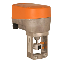
Selection of Control Valve Actuator
The electric actuator is selected based on the previously chosen control valve. It is recommended to choose electric actuators from the list of compatible devices specified in the valve characteristics.
- The connection nodes of the actuator and the valve should be compatible.
- The stroke of the electric actuator should be greater than or equal to the stroke of the valve.
- Depending on the inertia of the controlled system, actuators with different action speeds should be used.
- The maximum pressure difference on the valve at which the actuator can close it depends on the closing force of the actuator.
- The power supply voltage and control signal of the actuator should correspond to the power supply voltage and control signal of the controller.
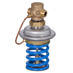
Calculation of the regulating valve for the possibility of cavitation
Cavitation is the formation of vapor bubbles in a water flow, which occurs when the pressure in the flow drops below the saturation pressure of water vapor. The effect of increasing flow velocity and decreasing pressure that occurs when the passage area narrows is described by the Bernoulli equation. The passage area of the regulating valve is such a narrowing, where the pressure can drop to the saturation pressure, and is the most likely place for cavitation to occur. Vapor bubbles are unstable, they appear suddenly and collapse just as quickly, leading to erosion of the valve metal, which will inevitably cause premature wear. In addition to wear, cavitation leads to increased noise during valve operation.
The main factors affecting cavitation:
- Water temperature - the higher it is, the more likely cavitation is to occur.
- Water pressure - before the regulating valve, the higher it is, the less likely cavitation is to occur.
- Allowable pressure drop - the higher it is, the more likely cavitation is to occur. It should be noted that in the closed position of the valve, the pressure drop across the valve tends to the excess pressure in the controlled section.
- Cavitation characteristic of the regulating valve - determined by the features of the throttling element of the valve. The cavitation coefficient is different for different types of regulating valves and should be indicated in their technical characteristics. However, since most manufacturers do not specify this value, the calculation algorithm includes a range of the most likely cavitation coefficients.
After checking for cavitation, the following results may be provided:
- 'None' - there will definitely be no cavitation.
- 'Possible' - cavitation may occur on the valves of certain constructions, it is recommended to change one of the aforementioned influencing factors.
- 'Present' - cavitation will definitely occur, change one of the factors that influence cavitation.
Calculation of the regulating valve for noise generation
High flow velocity in the inlet pipe of the regulating valve may cause high noise levels. For most rooms where regulating valves are installed, the permissible noise level is 35-40 dB (A), which corresponds to a velocity of approximately 3 m/s in the inlet pipe of the valve. Therefore, when choosing a regulating valve, it is recommended not to exceed the aforementioned velocity.
question : comment : feedback
 Online Equipment calculations