Please do not block ads on our site. Clicks on ads help us exist, grow and become more useful for you!
Calculation of Pressure Reducing Valve
 EXAMPLE


Calculation Methodology
The calculation of a reducing valve involves determining its flow capacity, required adjustment range, and checking for noise and cavitation.
Calculation of Flow Capacity
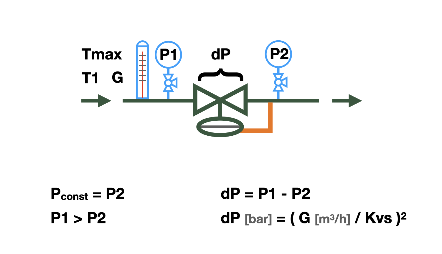
The relationship between pressure loss and water flow rate is called flow capacity, or Kvs.
Kvs - the flow capacity, is numerically equal to the flow rate in m³/hour through a fully open reducing valve when the pressure drop across the valve is 1 bar.
Kv - the same, for partial opening of the valve.
Knowing that when the flow rate changes by a factor of 'n,' the pressure drop across the valve changes by a factor of 'n²'' squared, it is easy to determine the required Kv of the reducing valve by substituting the design flow rate and excess pressure into the calculation equation.
Some manufacturers recommend selecting a reducing valve with the nearest higher Kvs value to the obtained Kv value. This approach allows for greater precision in regulating the flow below the calculated value, but does not allow for increasing the flow above the desired value, which is often necessary. We do not criticize the above method, but recommend selecting reducing valves in such a way that the required flow capacity is in the range of 50 to 70% of the stroke range. A reducing valve calculated in this way can accurately decrease the flow relative to the set value and slightly increase it as well.
The above calculation algorithm generates a list of reducing valves for which the required Kv value falls within the stroke range of 50 to 70%.
As a result of the selection process, a percentage of the reducing valve's opening is provided at which the desired excess pressure is throttled when a specified water flow rate is passed through.
Selection of Setting Range
The setting range of the relief valve depends on the spring compression force. Some relief valves are equipped with only one spring and have only one setting range for pressure, while others can be equipped with springs of different stiffness and have several setting ranges. The pressure that the relief valve will maintain should be within the range of adjustment.
Calculation of Cavitation Possibility
Cavitation is the formation of vapor bubbles in a water flow that occurs when the pressure in the flow drops below the saturation pressure of water vapor. The Bernoulli equation describes the effect of increasing the flow velocity and decreasing the pressure in it, which occurs when the flow passage is narrowed. The flow passage between the valve disc and the seat of the relief valve is the same narrowing, where the pressure may drop to the saturation pressure and the most likely place for cavitation to occur. The vapor bubbles are unstable, they appear suddenly and collapse just as abruptly, which leads to erosion of metal particles from valve components, inevitably causing premature wear. In addition to wear, cavitation leads to increased noise during the operation of relief valves.
The main factors that affect the occurrence of cavitation are:
- Water temperature - the higher it is, the more likely cavitation is to occur.
- Water pressure - before the relief valve, the higher it is, the less likely cavitation is to occur.
- Throttling pressure - the higher it is, the higher the likelihood of cavitation.
- Cavitation characteristic of the valve - determined by the features of the throttle element of the valve. The cavitation coefficient is different for different types of relief valves and should be indicated in their technical characteristics, but since most manufacturers do not specify this value, the calculation algorithm includes a range of the most likely cavitation coefficients.
After checking for cavitation, the following result may be issued:
- 'No' - cavitation will definitely not occur.
- 'Possible' - cavitation may occur on the valves of some designs, it is recommended to change one of the above-mentioned influencing factors.
- 'Yes' - cavitation will definitely occur, change one of the factors that affect cavitation.
Noise prediction calculation
High flow velocity in the inlet of the reducing valve may cause high noise levels. For most premises where reducing valves are installed, the permissible noise level is 35-40 dB (A), which corresponds to a velocity of approximately 3 m/s in the inlet of the valve. Therefore, when choosing a reducing valve, it is recommended not to exceed the mentioned velocity.
question : comment : feedback
 Online Equipment calculations