Please do not block ads on our site. Clicks on ads help us exist, grow and become more useful for you!
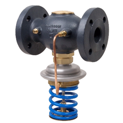
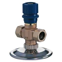
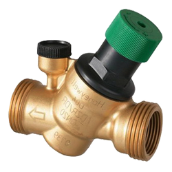
Calculation of Balancing Valve
 EXAMPLE


Method for calculating a balancing valve
In engineering systems, manual balancing valves are used to solve numerous tasks, such as limiting consumption, balancing circulation circuits, or simply throttling pressure. Regardless of the task, the calculation of a balancing valve comes down to determining its flow capacity, at which a given excess pressure drop will be throttled at a specified flow rate. In addition to compliance with flow capacity, the selected balancing valve must be checked for the possibility of cavitation and noise due to high water flow rates through it.
Calculation of the flow capacity of a balancing valve
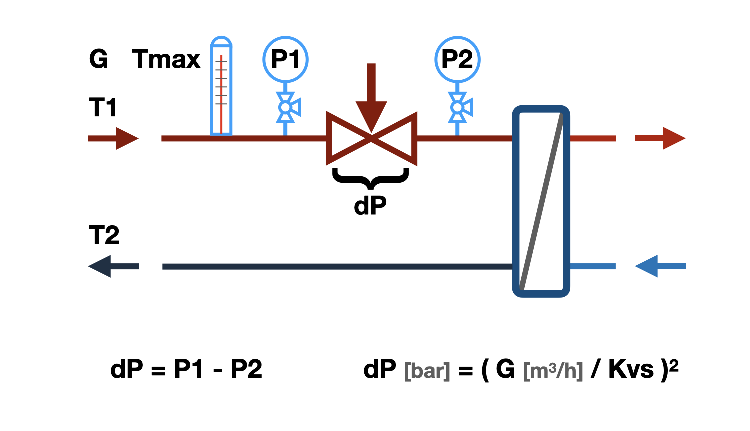
The dependence of pressure drop losses on flow through a balancing valve is called the flow capacity - Kvs.
Kvs - the flow capacity numerically equals the flow rate in m3/h, through a fully open balancing valve, at which pressure drop losses on it are equal to 1 bar.
Kv - the same, with partial valve opening.
Knowing that with a change in flow rate by N times, the pressure drop losses on the valve change by N squared times, it is not difficult to determine the required Kv of a balancing valve by substituting the calculated flow rate and excess pressure drop into the equation.
Some manufacturers recommend choosing a balancing valve with the nearest larger Kvs value to the obtained Kv value. Such an approach allows more accurate regulation of flow rate below the set value during selection, but does not allow increasing the water flow rate above the set value, which is often necessary to exceed. We do not criticize the above method, but we recommend selecting a balancing valve in such a way that the required flow capacity value is in the range of 50 to 70% of the stem travel. A balancing valve calculated in this way can both reduce the flow rate relative to the set one and slightly increase it with sufficient accuracy.
The above calculation algorithm outputs a list of balancing valves for which the required Kv value falls within the range of the stem travel of 50 to 70%.
In the search results, the percentage of opening the balancing valve shutter is given, at which the specified excess pressure is throttled at the specified flow rate. The given values are valid only for valves with a linear flow characteristic. The degree of opening of valves with a different characteristic will be different.
Calculation of balancing valve for cavitation possibility
Cavitation is the formation of vapor bubbles in a water flow that occurs when the pressure in the flow drops below the saturation pressure of water vapor. The Bernoulli equation describes the effect of increasing flow velocity and reducing pressure in a flow that occurs when the passage section is narrowed. The passage section between the valve and the seat of the balancing valve is this narrowing, in which the pressure can drop to the saturation pressure and is the most likely place for cavitation to occur. Vapor bubbles are unstable, they appear sharply and also collapse sharply, which leads to the erosion of metal particles from the valve, which will inevitably cause premature wear. In addition to wear, cavitation leads to an increase in noise during valve operation.
The main factors influencing cavitation:
- Water temperature - the higher it is, the more likely cavitation is to occur.
- Water pressure - in front of the balancing valve, the higher it is, the less likely cavitation is to occur.
- Throttled pressure - the higher it is, the higher the likelihood of cavitation.
- Cavitation characteristic of the balancing valve - determined by the features of the throttling element of the valve. The cavitation coefficient is different for different types of balancing valves and should be indicated in their technical specifications, but since most manufacturers do not indicate this value, the calculation algorithm includes a range of the most probable cavitation coefficients.
In the result of checking for cavitation, the following results may be obtained:
- [No] - cavitation will definitely not occur.
- [Possible] - cavitation may occur on the valves of some designs, it is recommended to change one of the influencing factors described above.
- [Yes] - cavitation will definitely occur, change one of the factors that influence the occurrence of cavitation.
Calculating the balancing valve for noise generation
High flow velocity in the inlet of the balancing valve can cause high noise levels. For most rooms where balancing valves are installed, the allowable noise level is 35-40 dB(A), which corresponds to a velocity of approximately 3m/s in the valve inlet. Therefore, when selecting a balancing valve, it is recommended not to exceed the above-mentioned velocity.
question : comment : feedback
Online Equipment calculations