Please do not block ads on our site. Clicks on ads help us exist, grow and become more useful for you!
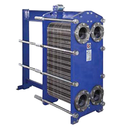
Heat exchanger Calculation for Heating Systems

 EXAMPLE


This online heat exchanger calculator will generate a request for selection of a heat exchanger for a heating system, and send it to manufacturers of plate heat exchangers, if desired.
Selection of Heat Exchanger
The selection of a heat exchanger involves choosing the shape, size, and number of plates, as well as the arrangement of the plates in the heat exchanger block. Due to many possible variations, even from a single manufacturer of heat exchangers, several different heat exchange devices can be selected for each request.
Plates for heat exchangers, manufactured by different companies, even with similar sizes, are not interchangeable and have only their own heat transfer properties. Therefore, heat exchangers from each manufacturer are selected using individual methods. Heat exchanger manufacturers do not disclose selection methods, even to their regional partners, providing only software that outputs the results after entering the input data.
Therefore, this online calculator will help you correctly formulate a request for a heat exchanger selection and send it to several manufacturers, if desired.
Calculation of a Heat Exchanger for a Heating System
In calculating a plate heat exchanger, heat losses from the apparatus casing are considered insignificant, meaning that it is assumed that all heat is transferred to the heat carrier in the circuit that heats and is transmitted to the heat carrier in the circuit being heated. Therefore, the thermal balance of the heat capacity between the two circuits must always be observed in the calculation.
The correctness of the thermal balance between the heating and heated circuits can be checked using the formula:
Q[kW] = 1.163 · G[t/h] · dt[°C]
The obtained values of the amount of heat after the parameters of both circuits are substituted should be equal.
When calculating a plate heat exchanger for a heating system, the input data are the heat capacity of the heating system, the design temperature curve of the heating system, and the heat source. As a result of the calculation, the flow rate of the heat carrier in the heating and heated circuits is determined.
The main feature of calculating a heat exchanger for a heating system is that the heat exchanger must provide correct operation in both maximum and transitional operating modes.
The maximum mode is considered to be the mode with a calculated outdoor temperature for the heating system (for Kiev, this is -22°C). In the design mode, the heat carrier comes from the heat source with the maximum temperature at the peak (if the source is a thermal network, it can be 120/70°C, i.e., 120°C in the supply and 70°C in the return, or in an autonomous boiler house, the mode of 95/70°C can be accepted). In the design mode, water enters the heating system with the maximum temperature at the peak of the temperature curve, for example, 90/70°C or 80/60°C, depending on the chosen design.
The transitional mode is considered to be the mode with the average outdoor temperature during the heating period in the city where the heat exchanger is planned to be installed (for Kiev, this is -0.1°C). The temperatures of the heat carrier in the transitional mode at the input of the heat source and at the input to the heating system are lower and are determined from the temperature curve at the corresponding outdoor temperature.
For residents of Ukraine, the option of selecting a city is available, and the outdoor temperatures for the design and transitional modes will be automatically selected according to DSTU-N B V.1.1-27:2010 'Building Climatology' while residents of other countries will need to enter temperatures manually.
Several common mistakes when filling out the calculation form
1 The temperature of the water leaving the heat exchanger must be higher than the temperature of the incoming water being heated at all operating modes. Otherwise, the size of the heat exchanger will be infinitely large.
This means that if your heat source operates at a temperature regime of 130/70 °C, and the calculated temperature regime for the heating system is 90/70 °C, then either the temperature of the water leaving the heat exchanger should be increased, for example, to 130/80 °C, or a lower temperature regime should be accepted for the heating system, for example, 80/60 °C. Building codes (DBN) allow for an increase in the temperature of the heat carrier in the return pipeline of the heat source by 5-10°C when the heating system is connected through a heat exchanger.
2 Do not set the allowable pressure drop in the heat exchanger to less than 10 kPa (1 m) unless it is an essential condition. The smaller the allowable pressure drop, the larger the heat exchanger, and consequently, its cost.
question : comment : feedback
 Online Equipment calculations