Please do not block ads on our site. Clicks on ads help us exist, grow and become more useful for you!
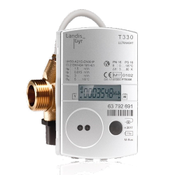
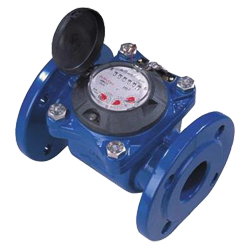
Calculation of Heat Meter
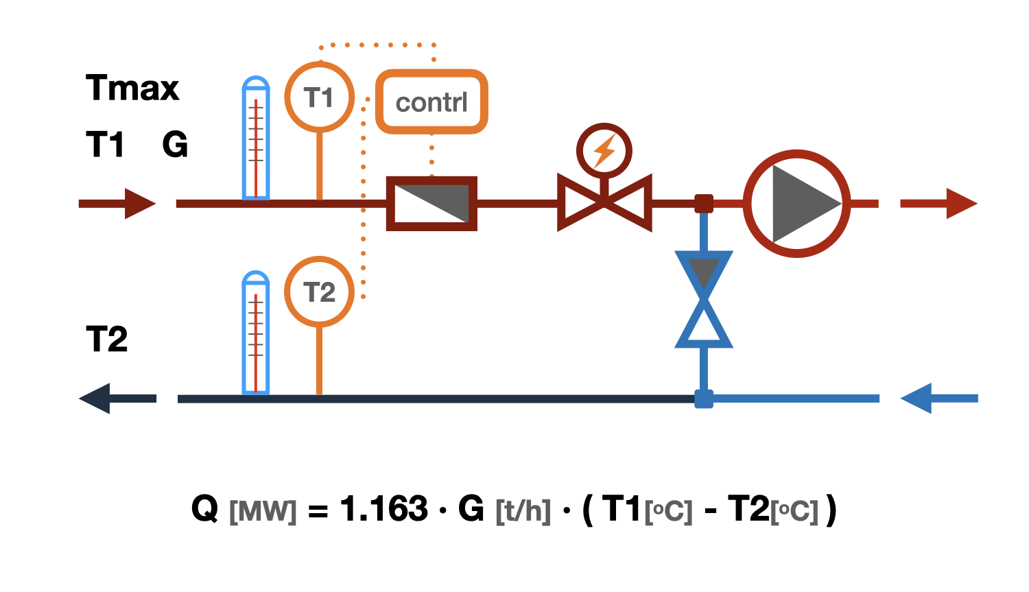
 EXAMPLE


Selection of Heat Meters
The selection of a heat meter is carried out taking into account the technical conditions of the heat supply organization and the requirements of regulatory documents. Usually, requirements are set for:
- metering scheme
- composition of the metering unit
- measurement errors
- composition and depth of the archive
- dynamic range of the flow sensor
- availability of data acquisition and transmission devices
Only certified heat meters registered in the State Register of Measuring Equipment are allowed for commercial calculations. It is prohibited to use flow sensors with a dynamic range of less than 1:10 for commercial calculations as part of heat meters.
Calculation of Heat Meters
The calculation of a heat meter consists in selecting the type and size of the flow meter. Many people mistakenly believe that the diameter of the flow meter should correspond to the diameter of the pipe on which it is installed.
The diameter of the flow meter of the heat meter should be selected based on its technical characteristics.
- Qmin - minimum water flow rate, m³/hour
- Qt - transitional water flow rate, m³/hour
- Qn - nominal water flow rate, m³/hour
- Qmax - maximum allowable water flow rate, m³/hour
It is recommended to select flow meters as part of heat meters in such a way that the calculated flow rate of the heat carrier falls within the range from Qt to Qn, and for flow meters of the second accuracy class (for which the value of Qt is not specified), within the range of flows from Qmin to Qn.
When selecting flow meters, it is necessary to take into account the possibility of reducing the flow rate of the heat carrier through the heat meter associated with the operation of the regulating valve, and the possibility of increasing the flow rate of the heat carrier through the heat meter associated with the instability of the temperature and hydraulic regime of the heating network. Regulatory documents recommend selecting a heat meter with the closest value of the nominal flow rate Qn to the calculated flow rate of the heat carrier. This approach to selecting a heat meter practically eliminates the possibility of increasing the flow rate of the heat carrier above the calculated value, which is often necessary to do in real conditions of heat supply.
The above algorithm outputs a list of heat meters that, with the declared accuracy, will be able to take into account the flow rate of the heat carrier one and a half times higher than the calculated one and three times less than the calculated one.
Calculation of the flow rate through a heat meter
The flow rate of the heat carrier is calculated using the following formula:
G = (3.6 · Q)/(4.19 · (t1 - t2)), kg/h
where
- Q - thermal power of the system, W
- t1 - temperature of the heat carrier at the inlet to the system, °C
- t2 - temperature of the heat carrier at the outlet from the system, °C
- 3.6 - conversion factor from W to J
- 4.19 - specific heat capacity of water, kJ/(kg K)
Calculation of the heat meter for the heating system
The flow rate of the heat carrier for the heating system is calculated using the above formula, while the calculated thermal load of the heating system and the calculated temperature are substituted into it.
The design heat load of the heating system is usually specified in the contract with the heat supply organization and corresponds to the thermal capacity of the heating system at the design outdoor temperature (for Kiev -22°C).
The design temperature regime is also specified in the same contract with the heat supply organization and corresponds to the temperatures of the heat carrier in the supply and return pipelines at the same design outdoor temperature. Temperature mode of 150-70, 130-70, 110-70, 95-70, and 90-70 are most commonly used, although other parameters are possible.
Calculation of heat meter for hot water supply system
For a closed circuit water heating system (through a heat exchanger), the heat meter is installed in the circuit of the heated water
Q - The thermal load on the hot water supply system is taken from the heat supply contract.
t1 - Is assumed to be equal to the minimum temperature of the heat carrier in the supply pipeline, also specified in the heat supply contract. It is usually 70 or 65°C.
t2 - The temperature of the heat carrier in the return pipeline is assumed to be 30°C.
For a closed circuit water heating system (through a heat exchanger), the heat meter is installed in the circuit of the heated water
Q - The thermal load on the hot water supply system is taken from the heat supply contract.
t1 - Is assumed to be equal to the temperature of the heated water at the outlet of the heat exchanger, which is usually 55°C.
t2 - Is assumed to be equal to the temperature of the water at the inlet of the heat exchanger in the winter period, which is usually 5°C.
Calculation of heat meter for multiple systems
When installing one heat meter for multiple systems, the flow rate through it is calculated as the sum of the flow rates of the heat carrier calculated for each system separately.
The flow meter is selected in such a way that it can take into account both the total water flow rate when all systems are operating simultaneously and the minimum flow rate when only one system is operating.
question : comment : feedback
Online Equipment calculations