Please do not block ads on our site. Clicks on ads help us exist, grow and become more useful for you!
Installation diagrams of three-way valves
Three-way valve diagrams are used in control nodes:
- Connected to a low-pressure collector.
- With a low pressure drop at the heat source inlet.
- With the heat source temperature regime identical to the consumer temperature regime.
- Requiring constant circulation support in one of the circuits.
- Requiring quality regulation by mixing two flows of the heat carrier.
- Requiring quantity regulation by splitting the flow of the heat carrier.
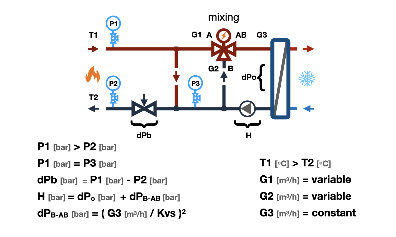
In heat points connected to centralized heating networks, mixing three-way valves have not found wide application due to the impossible limitation of the heat carrier flow rate while maintaining the mixing coefficient, and dividing three-way valves due to the bypass of the heat carrier from the supply to the return pipeline.
Mixing three-way valve installation diagram

This diagram provides quality regulation in the consumer. At the same time, the heat carrier flow through the source can be completely stopped. It is used in boiler rooms to connect the heating system to a low-pressure collector or hydraulic distributor (hydraulic arrow). A pump in the heating system circuit provides circulation through the heating system and through the heat source.
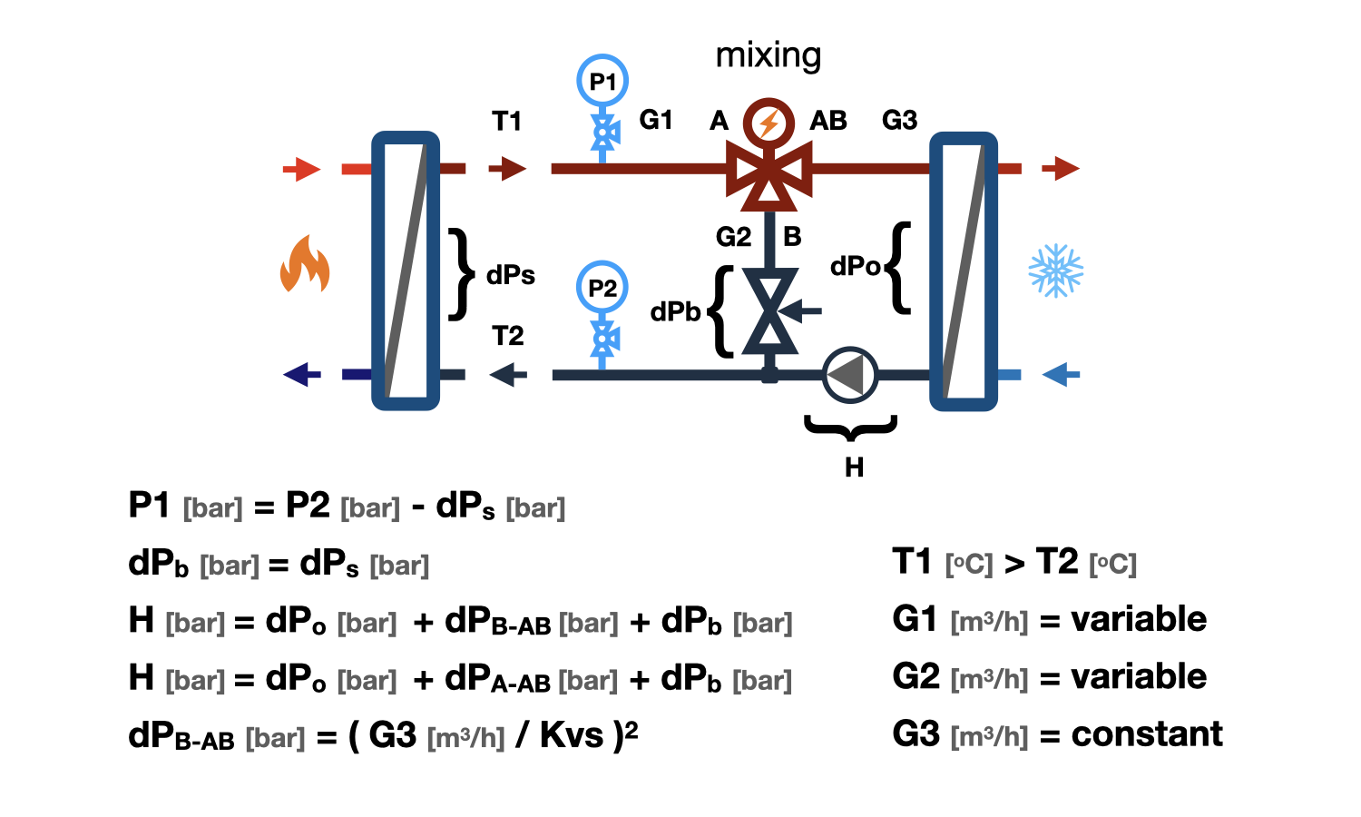
Important! - In the case of direct connection to the heat source on the bypass pipeline of the three-way valve connected to port (B), it is necessary to install a balancing valve with hydraulic resistance equal to the resistance of the heat source. Otherwise, the heat carrier flow rate in the AB port may vary significantly depending on the stroke direction. Also, it should be noted that this scheme does not exclude the complete cessation of heat carrier circulation through the heat source when connecting without a hydraulic distributor and its own circulation pump in the heat source circuit.

Important! - It is not recommended to connect a three-way valve according to this scheme to a pressure collector or heating networks without devices for throttling excess pressure. Otherwise, the heat carrier flow rate through the AB port may vary significantly over a wide range.
If the heat source operating conditions allow or even recommend overheating the return flow, excess pressure is eliminated by installing a jumper parallel to the mixing three-way valve in the heat source circuit.
Installation diagram of a separating three-way valve
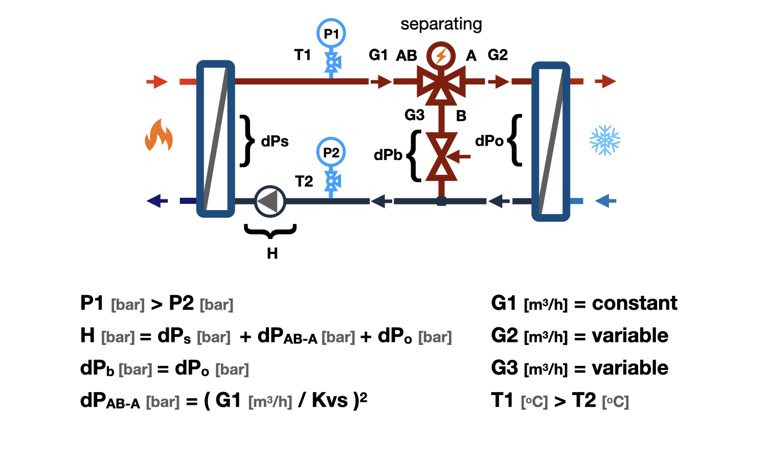
Provides quantitative regulation at the consumer by changing the flow rate of the heat carrier. Used when operating conditions of the heat source allow for the return of the heat carrier to the return pipeline and do not allow for the circulation to be stopped in the heat source circuit.
This installation diagram of a three-way valve is widely used in water and air heating nodes connected to an autonomous boiler room.
To connect hydraulic circuits, the pressure loss on the balancing valve in the bypass line must be equal to the pressure loss at the consumer.
This installation diagram of a three-way valve is designed for connection to a pipeline with excess pressure. The circulation of the heat carrier in the consumer circuit is provided by the excess pressure created by the circulation pump in the heat source circuit.
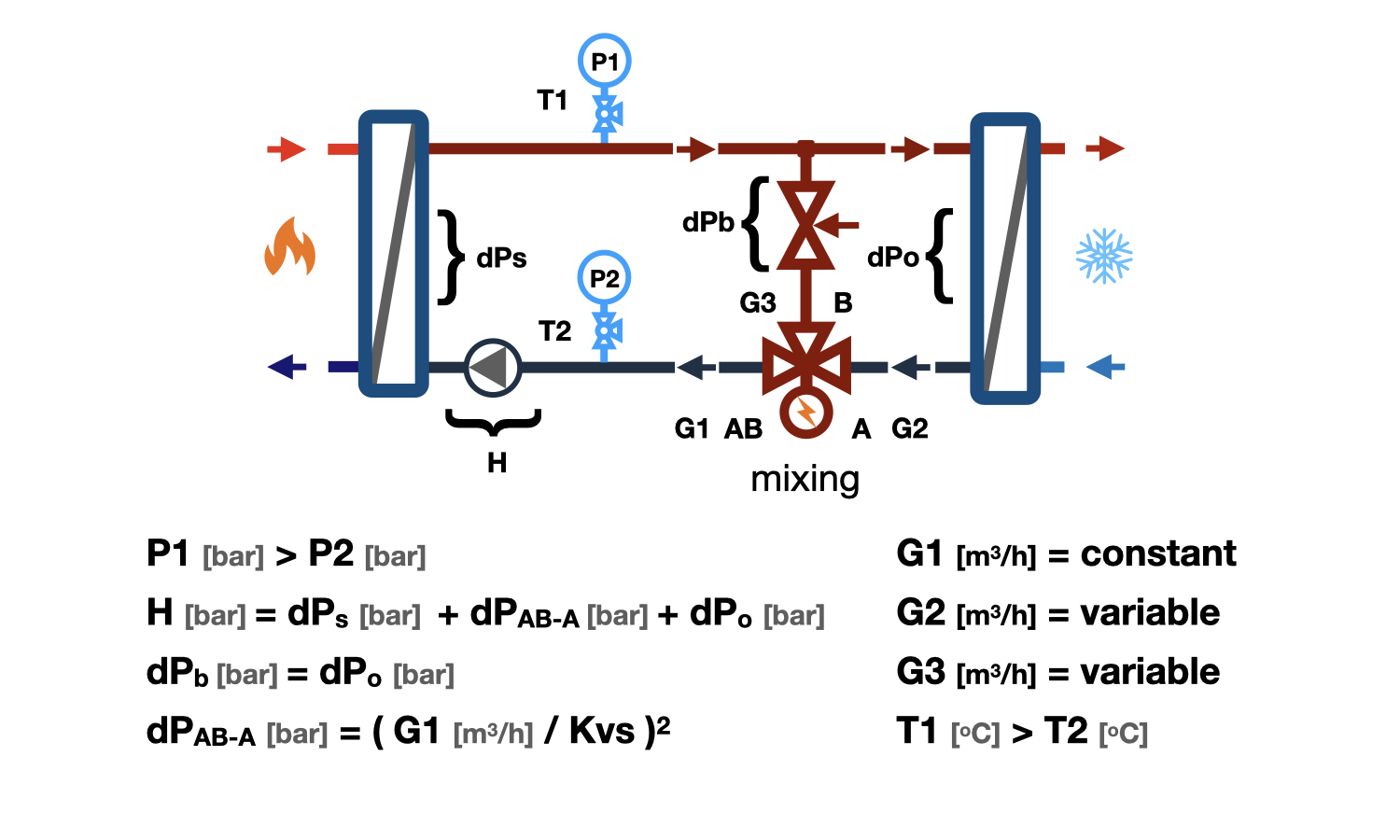
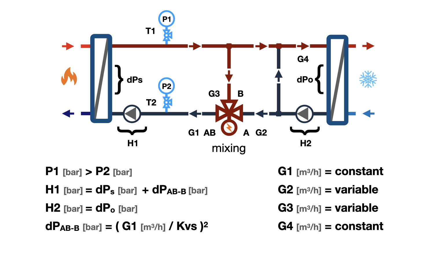
Installation schemes of a mixing three-way valve for separation
Provides quantitative regulation in the consumer's system by using a mixing three-way valve. It is used when the operating conditions of the heat source do not allow for the flow to be stopped in the heat source circuit, and the return of the heat carrier to the reverse pipeline is allowed.
Similar connection schemes for three-way valves are widely used in the installation of air heaters and coolers, as well as in water heating nodes installed in autonomous boiler rooms.
A balancing valve with hydraulic resistance equal to that of the consumer should be installed on the mixing port of the three-way valve. The circulation through the consumer and bypass is carried out by means of the excess pressure in the heat source circuit. With the correct selection of the valve and hydraulic connection of the bypass with the consumer circuit, the flow through the heat source is constant and variable in the consumer circuit.
When connecting a node with a separating three-way valve to the heat source directly or to a non-pressure collector, a circulation pump is required in the supply or return pipeline. The pump can be common to several circuits.
This connection scheme of a three-way valve that separates the flow with an additional bypass in the consumer circuit is used when the temperature regime of the heat source exceeds the temperature regime of the consumer. The feature of this scheme is that the flow rates in the heat source and consumer circuits will be constant, and the overheated heat carrier will not reach the consumer. The consumer will be provided with high-quality regulation. To operate this scheme, a pump is required in the consumer circuit and in the heat source circuit.


 Tutorial Belimo
question : comment : feedback
2674
 Catalog of
