Please do not block ads on our site. Clicks on ads help us exist, grow and become more useful for you!
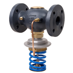
Calculation of Pressure Relief Controller
 EXAMPLE


Methodology for calculating Pressure Relief Controller
The calculation of the pressure relief regulator involves determining the regulator's required flow capacity, necessary adjustment range, and checking for the possibility of noise and cavitation.
Calculation of Flow Capacity
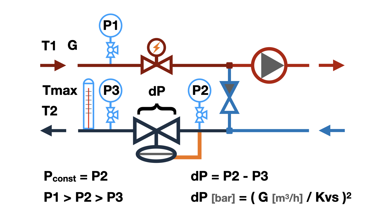
The dependence of pressure loss on water flow through the pressure regulator is called flow capacity - Kvs.
Kvs - the flow capacity numerically equals the water flow rate in m³/hr through a fully open pressure relief controller at which the pressure loss on it equals 1 bar.
Kv - the same at partial opening of the pressure regulator valve.
Knowing that when the flow changes 'n' times, the pressure loss on the regulator changes 'n²' times in square, it is not difficult to determine the required Kv value of the pressure regulator by substituting the calculated water flow rate and excess pressure into the equation.
Some manufacturers recommend selecting a pressure regulator with the nearest higher Kvs value from the obtained Kv value. This selection approach allows for more precise regulation of water flow below the calculated value, but does not allow for increasing flow. We recommend selecting pressure relief regulator such that the required flow capacity value is in the range of 50 to 70% of the stem stroke. A pressure regulator calculated in this way can both decrease flow with sufficient accuracy compared to the set value and slightly increase it.
The above calculation algorithm generates a list of pressure relief controllers for which the required Kv value falls within the stem stroke range of 50 to 70%.
As a result of the selection, the percentage of valve opening of the pressure regulator is given at which excess pressure is throttled at the specified flow rate.
Selection of pressure regulator
The adjustment range of the pressure regulator depends on the spring compression force. Some regulators are equipped with only one spring and have only one adjustment range, while others may be equipped with springs of different stiffness and have several adjustment ranges. The pressure that the regulator will maintain should be approximately in the middle third of the adjustment range. The algorithm outputs a list of regulators in which the set pressure will fall within the range of 20 to 80% of the supported pressures range.
When choosing the adjustment range, it is necessary to take into account that the permissible calibration error of the spring at the boundaries of the adjustment range is 10%.
Calculation of pressure relief controller for cavitation prevention
Cavitation is the formation of vapor bubbles in a water stream, which occurs when the pressure in it drops below the saturation of water vapor. The effect of increasing the flow rate and decreasing the pressure in it, which occurs when the passage cross-section is narrowed, is described by Bernoulli's equation. The passage section of the support regulator is the narrowing where the pressure can drop to the saturation pressure, and the most likely place for cavitation to occur. Vapor bubbles are unstable, they suddenly appear and also suddenly collapse, which leads to the erosion of metal particles from the regulator elements, which will inevitably cause its premature wear. In addition to wear, cavitation leads to an increase in noise when the regulator is in operation.
- The water temperature - the higher it is, the higher the probability of cavitation.
- The water pressure - before the regulator, the higher it is, the lower the probability of cavitation.
- The throttling pressure - the higher it is, the higher the probability of cavitation.
- The cavitation characteristic of the regulator is determined by the features of the throttling element of the regulator. The cavitation coefficient is different for different types of pressure regulators and should be indicated in their technical characteristics, but...
As a result of the cavitation test, the following results may be issued:
- 'No' - cavitation will definitely not occur.
- 'Possible' - cavitation may occur on the valves of certain designs, it is recommended to change one of the above-mentioned factors affecting cavitation.
- 'Yes' - cavitation will definitely occur, change one of the factors affecting cavitation.
Calculation of the noise generation by the pressure relief controller
High flow velocity in the inlet flange of the pressure regulator can cause high noise levels. For most of the rooms in which pressure regulators are installed, the allowable noise level is 35-40 dB(A), which corresponds to a velocity of approximately 3 m/s in the inlet flange of the valve. Therefore, when choosing a support regulator, it is recommended not to exceed the above-mentioned velocity.
question : comment : feedback
 Online Equipment calculations