Please do not block ads on our site. Clicks on ads help us exist, grow and become more useful for you!
Installation of balancing valve
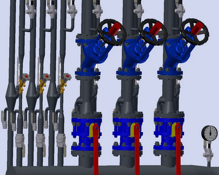
Installation of balancing valve is carried out in accordance with the installation instructions, in addition, the following recommendations should be taken into account:
- A strainer should be installed before the valve.
- Pressure gauges are recommended to be installed before and after the valve.
- The installation position can be any, as long as it does not contradict the installation instructions.
- The arrow on the body should coincide with the direction of the water flow at the installation location of the valve.
- The body of the balancing valve should not be subjected to bending, torsion, stretching, or compression loads.
- The installation location of the balancing valve should be accessible for maintenance, adjustment, and flow measurement.
- Different manufacturers provide different data, but on average, it is recommended to maintain straight sections of 5DN before and 10DN after the manual balancing valve.
Sequence for packing a threaded connection
1. Take a flax fiber string with enough threads so that its twisted diameter is approximately equal to the depth of the thread. The length of the string should provide for 1.5-2 times more windings than the number of thread turns.
2. Starting approximately 50-70 mm from the beginning of the string, slightly twist it, place it in the first thread turn, and, holding it with your hand, tightly wind a long branch of the string clockwise, placing it in each thread turn.
3. When reaching the end of the thread, continue winding with a second layer, shifting the turns to the beginning of the thread. The length of the second layer winding should be approximately equal to 2/3 of the thread length.
4. Wind the remaining end of the string (50-70 mm) similarly clockwise, from the end of the thread to its beginning.
5. Apply a layer of sealant to the winding surface.
6. Tighten the connecting elements by hand. With correct packing, the assembled element should turn 1.5-2 full rotations.
7. Continue tightening the element with a wrench or a torque wrench. In case the assembled element needs to be in a specific position, complete tightening it in the necessary position of the element.
With proper packing, during tightening, the force should not exceed the tightening torque listed below:
| DN15 | DN20 | DN25 | DN32 | DN40 | DN50 | DN65 | DN80 | DN100 |
|---|---|---|---|---|---|---|---|---|
| 70 Nm | 95 Nm | 120 Nm | 150 Nm | 190 Nm | 230 Nm | 280 Nm | 350 Nm | 400 Nm |
Tightening torques for flange connections
| DN | Nut/Bolt | Torque, Nm |
|---|---|---|
| 15 - 32 | М 10 | 15 - 30 |
| 40 - 65 | М 12 | 35 - 50 |
| 80 - 100 | М 16 | 75 - 100 |
| 125 - 150 | М 16 | 80 - 120 |
| 200 | М 20 | 150 - 200 |
| 250 - 400 | М 24 | 340 - 410 |
| 500 | М 27 | 340 - 410 |


 Tutorial Danfoss
question : comment : feedback
429
 Catalog of
 balancing valves
Zetkama
Zetkama
Herz
Herz
Herz
Herz
Herz
Herz
Herz
Herz
Danfoss
Danfoss
Danfoss
Danfoss
Danfoss
IMI Hydronic
IMI Hydronic
IMI Hydronic
IMI Hydronic
IMI Hydronic
IMI Hydronic
Honeywell - Resideo
Honeywell - Resideo
Honeywell - Resideo
Honeywell - Resideo
Oventrop
Oventrop
Oventrop
Frese
ARI Armaturen
ARI Armaturen
VIR
VIR
VIR
Vexve
Vexve
Danfoss
Danfoss
IMI Hydronic
IMI Hydronic
IMI Hydronic
IMI Hydronic
Zetkama
Zetkama
VIR
Comap
Comap
Comap
Herz
Vexve
Vexve
Broen
Broen
Broen
Broen
Broen
Broen

