Please do not block ads on our site. Clicks on ads help us exist, grow and become more useful for you!
Installation schemes of heat meters
Below are the most common schemes for installing heat meters in heating and water supply systems of residential and public buildings, as well as in industrial facilities:
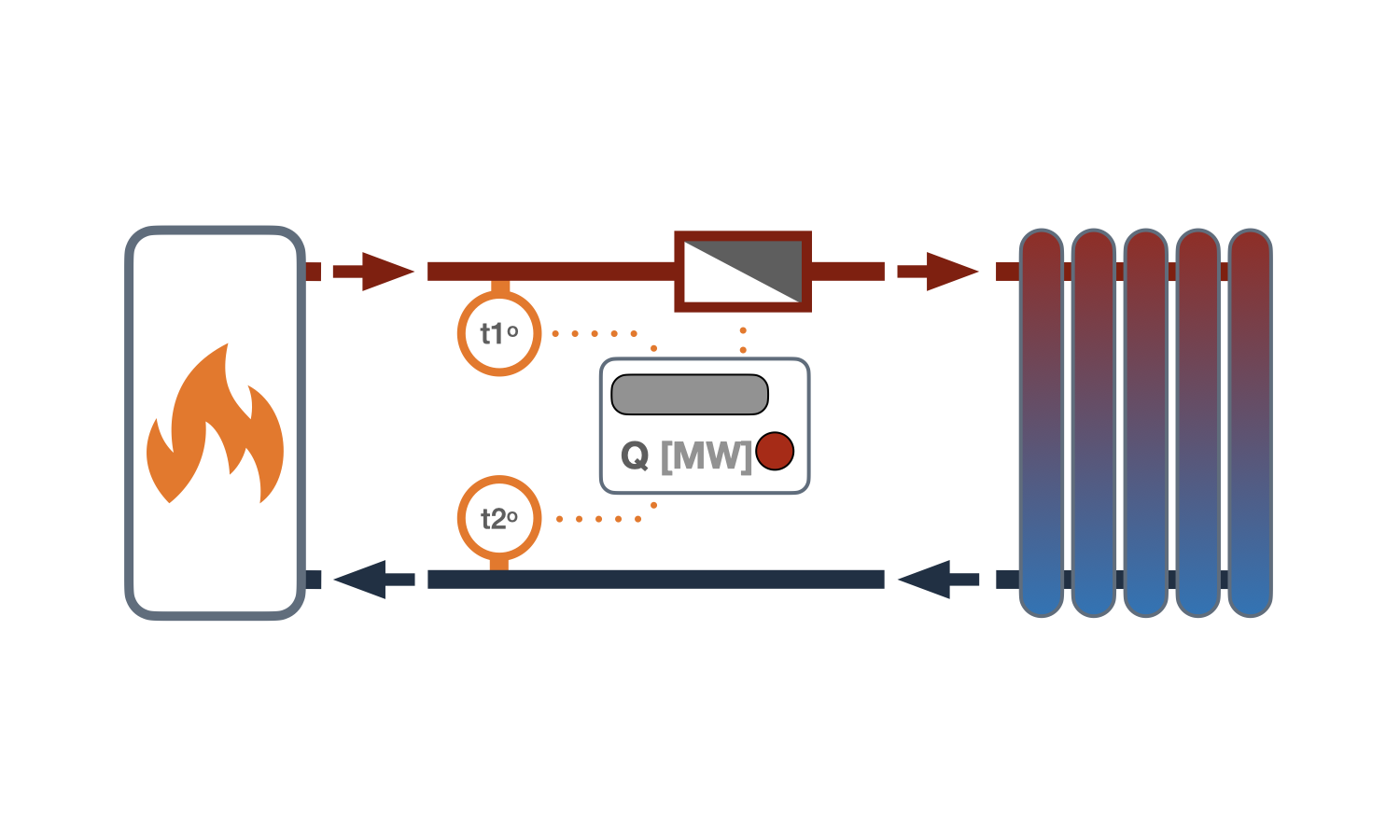
1 Scheme - with a single-channel heat meter — equipped with a calculator, one flow meter, and two temperature sensors. The meter flow sensor is installed in the supply pipe, and the temperature sensors are installed in the supply and return pipes.
The advantage of this scheme is the requirement for a meter with the smallest set of equipment and, as a result, the lowest price. The disadvantage is the inability to control leaks and unauthorized withdrawal of the heat carrier.
This is the most common scheme for installing a heat meter, which is used for commercial metering in heating systems of residential and administrative buildings.
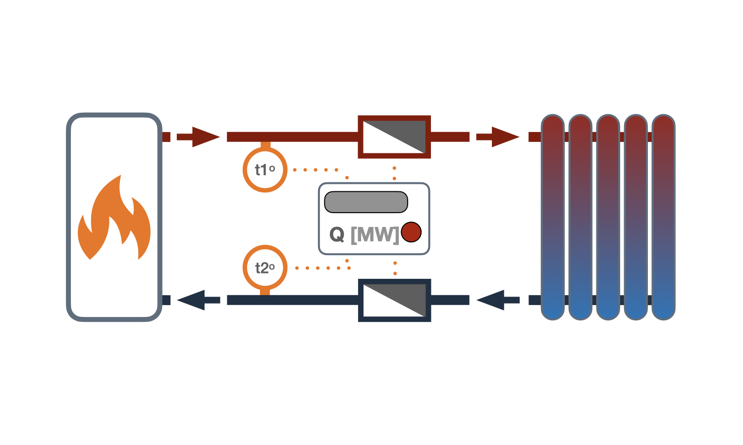
2 Scheme - with a single-channel heat meter and a control water meter — equipped with a calculator, two flow meters, and two temperature sensors. The flow meters and temperature sensors are installed on the supply and return pipelines.
This scheme is free from the disadvantages inherent in the first scheme and allows for taking into account the volume of heat carrier leakage, but does not take into account the amount of heat expended on heating the leaked water.
The amount of heat is determined based on the data from one flow meter and two temperature sensors, and the data on the flow obtained from the second flow meter is compared with the indicators of the first meter to determine the heat carrier leakage.
These schemes are used in objects:
- with a high probability of water withdrawal from heating systems;
- with underground piping after the heat meter installation point;
- with a combined metering of heat for heating and hot water supply using a single heat meter;
- with water heating installations for the hot water supply system connected in a closed circuit (through heat exchangers).
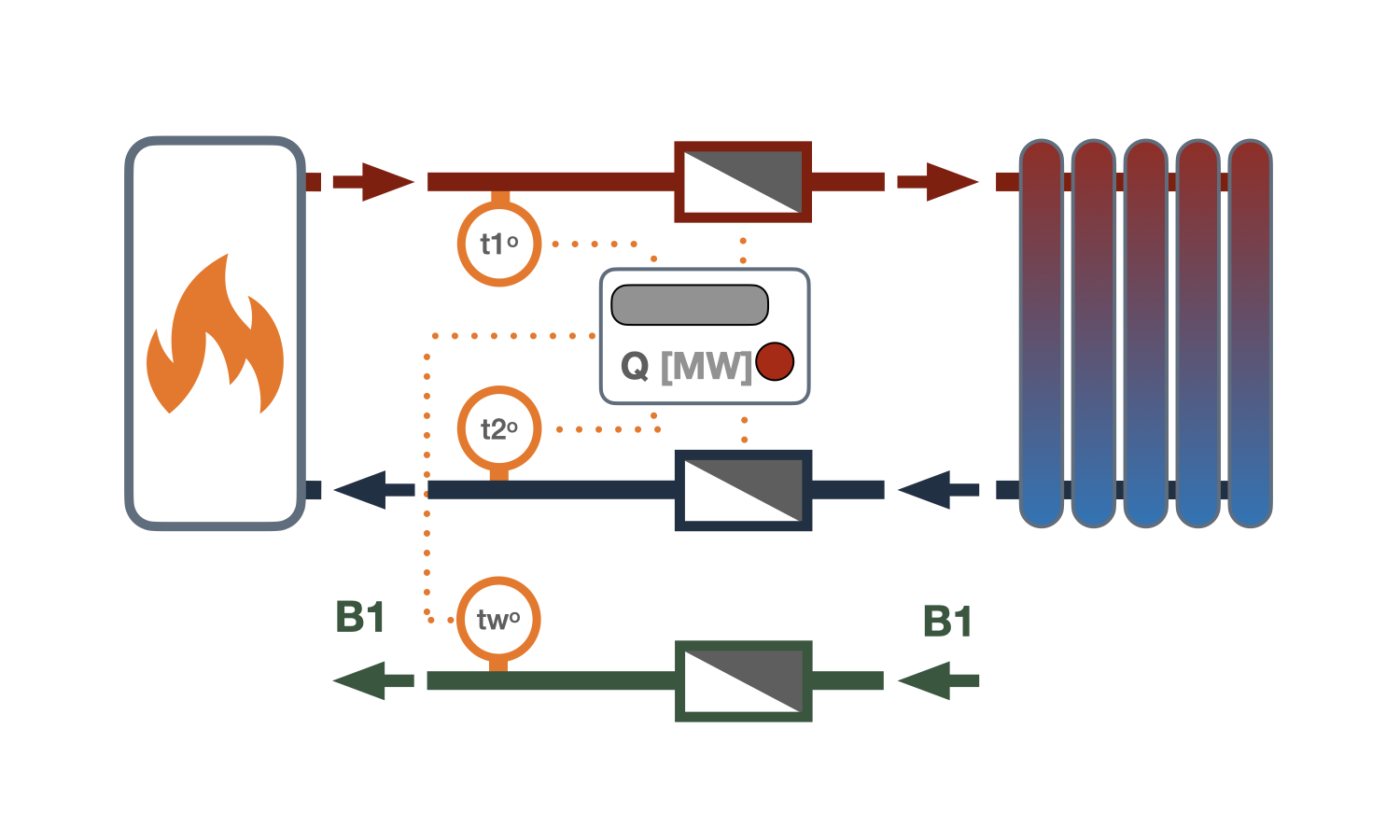
3 Scheme - with a two-channel heat meter — equipped with a calculator, two flow meters, and three temperature sensors. Flow meters are installed on the supply and return pipelines, and temperature sensors on the supply, return, and cold water supply pipelines.
This scheme is used to measure heat consumption from the heat source to the consumer.
The released heat is determined as the difference between the heat calculated using the first channel and the heat calculated using the second channel:
- The first channel - uses data on consumption from the meter installed on the supply pipeline and the temperature difference between the sensor installed in the supply pipeline and the cold water supply pipeline.
- The second channel - uses data on consumption from the meter installed on the return pipeline and the temperature difference between the sensor installed in the return pipeline and the cold water supply pipeline.
This heat meter installation scheme determines the released heat, taking into account the heat used to heat water for the system. A water meter needs to be installed on the supply pipe for this scheme. The water meter is not connected to the heat meter.


question : comment : feedback
answer
459
 Catalog of
 heat meters
Landis Gyr
Landis Gyr
DIEHL
Kamstrup
Kamstrup
Zenner
Zenner
AXIOMA Metering
AXIOMA Metering
Аква Украина
Engelmann
Семпал
Семпал
Sensus
Sensus
ИТ
Sontex
Maddalena
Itron
Danfoss
Danfoss
Danfoss
Kamstrup
Kamstrup
Kamstrup
Sontex
Sontex
Sontex
Sontex
DIEHL
DIEHL
Sensus
Sensus
Sensus
Sensus
Sensus

