Please do not block ads on our site. Clicks on ads help us exist, grow and become more useful for you!
Pipe span calculation
calculation of distances between pipeline supports
 EXAMPLE
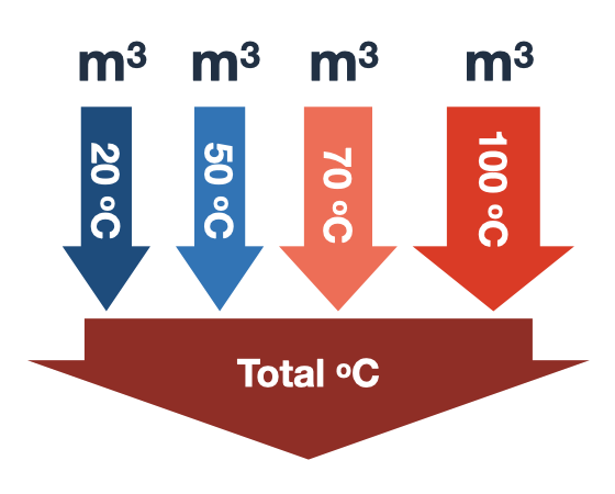
Pipe support spacing is selected based on calculations of strength and deflection, depending on the laying method, parameters of the heat carrier, diameter, and material of the pipeline.
The calculation of the spacing between supports for steel pipelines is performed using tabulated data provided in the designer's handbook «Design of Heat Networks».
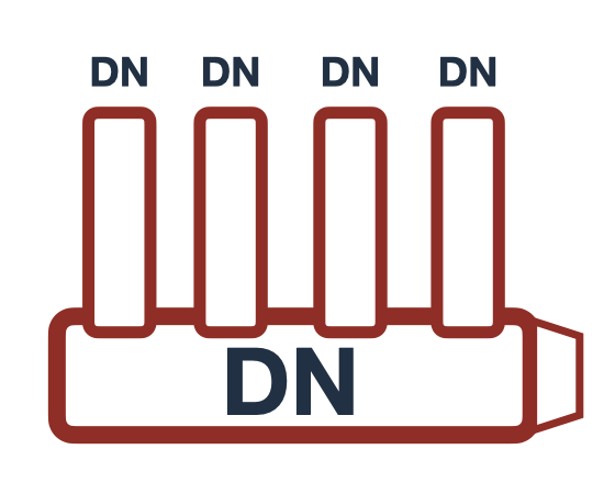
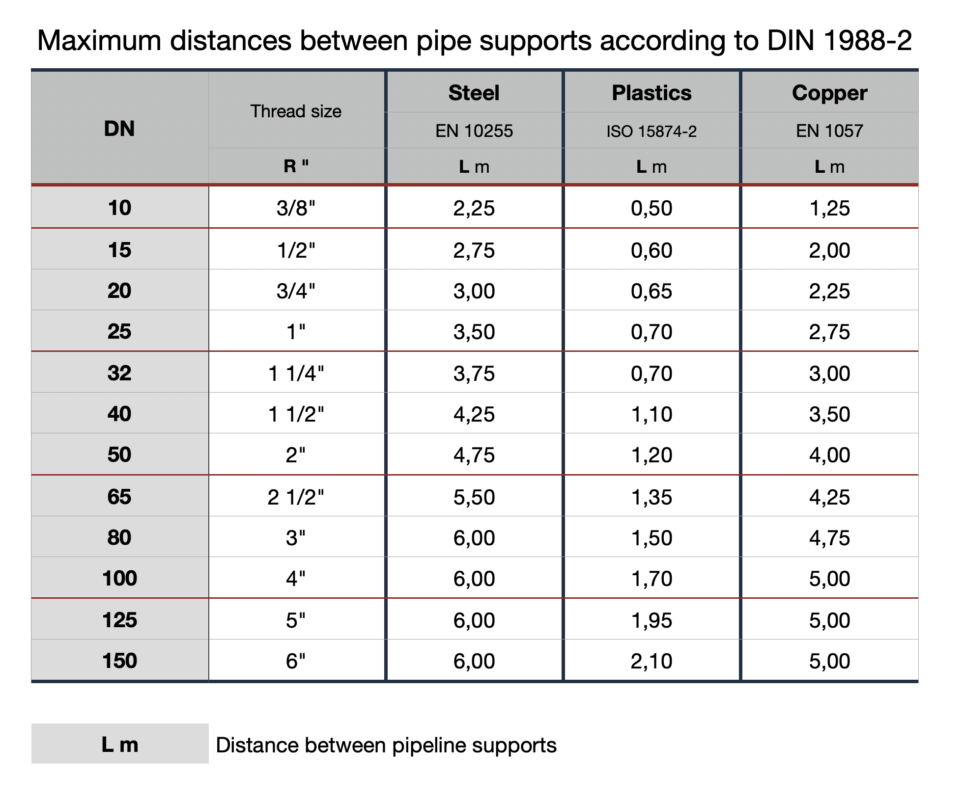
Spans between supports for plastic and copper pipelines are calculated based on the maximum spans specified in DIN 1988-2.
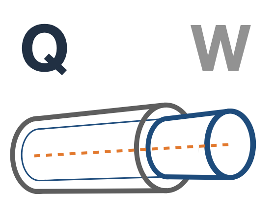
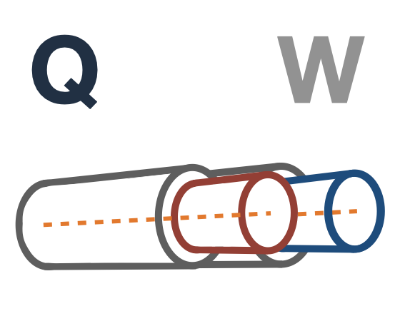
The arrangement and combination of movable and fixed supports during pipeline laying design are critical for ensuring stability, efficiency, and durability of the system. This helps avoid pipe deformations during thermal expansion, ensures safe operation, and minimizes the risk of accidents and leaks.
Movable supports are installed between fixed supports to allow pipe displacement during temperature expansion. The placement of fixed supports depends on the schematic features of the heat networks. Typically, fixed supports are installed at pipe branches and near shut-off valves, while on straight sections, they are positioned considering the compensating capacity of compensators and self-compensating sections.
This online calculation will determine the following distances between pipeline supports:
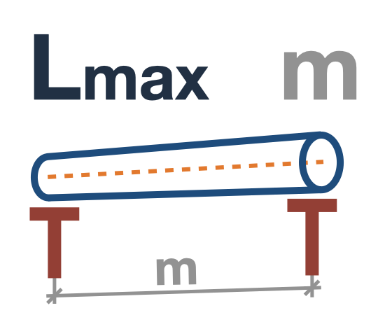
- maximum span for strength calculation on straight sections
- maximum span for deflection calculation on straight sections
- recommended distance between pipe supports on straight sections
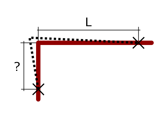
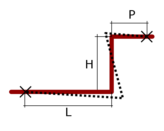
- distance between pipeline supports at sections adjacent to compensators and turns
Selection of movable support for steel pipes
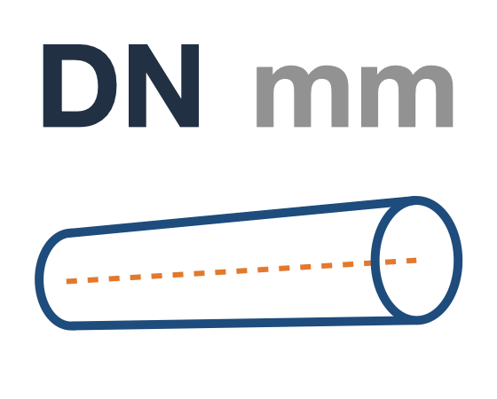
Sliding supports: are used for pipes ranging from DN25 to DN150 in all variants of heat network laying. For pipes with a diameter of DN200 – 1200 mm, sliding supports are used when laying in non-accessible and semi-accessible channels, as well as for the bottom row of pipes in tunnels.
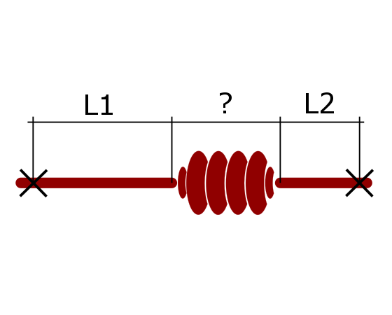
Suspension supports: are used for above-ground laying on viaducts with spans, suspending one pipe to another, on self-compensating sections, or when installing U-shaped compensators. When using U-shaped compensators, it is recommended to install guiding supports at a distance of 40*DN. Installation of suspension supports is not allowed on sections with axial compensators.
Roller supports: are used for pipes with a diameter of DN > 200 mm when laying on low and high supports, separately standing, along building walls, and in tunnels on frames and brackets. Roller supports are not used when laying pipelines in non-accessible channels.
For above-ground laying of pipelines on viaducts with spanning structures, both sliding and roller supports are used for nominal pipe diameters DN > 200 mm. Roller supports are installed if the use of sliding supports leads to overloading of spans.
Movable supports are not used for trenchless pipeline laying.
 Online Calculations