Please do not block ads on our site. Clicks on ads help us exist, grow and become more useful for you!
Installation of the differential pressure controller
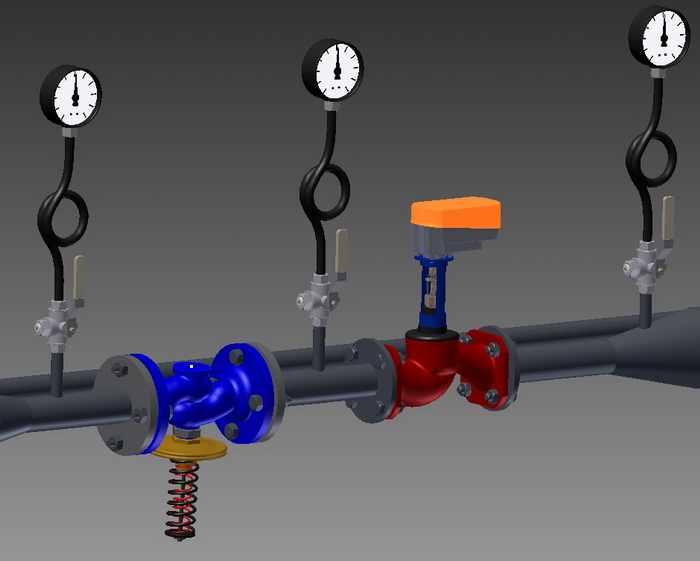
Installation of the differential pressure controller is carried out according to the installation instructions, and the following recommendations should also be considered:
- Pressure gauges should be installed before and after the controller.
- A Y-strainer should be installed before the differential controller in the direction of water flow.
- For installation on a pipeline carrying high-temperature water, an impulse cooler and a stem cooler may be required.
- Different manufacturers provide various recommendations, but generally, it is advised to have 5DN of straight piping before and 10DN after the controller during installation.
- For most differential pressure controllers, the recommended installation position at temperatures above 80°C is horizontal with the diaphragm actuator facing down; below 80°C, installation can be in any position.
Threaded joint packing sequence
1. Take a bundle of flax fiber of sufficient thickness that its twisted diameter approximately equals the thread depth. The length should allow for wrapping 1.5-2 times the number of thread turns.
2. Starting approximately 50-70 mm from the end, twist the bundle slightly, place it in the first thread turn, and, holding it firmly, wrap tightly clockwise, placing it in each thread turn.
3. Upon reaching the end of the thread, continue wrapping back towards the thread start, covering about 2/3 of the thread length with a second layer.
4. Wrap the remaining bundle end (50-70 mm) clockwise from the thread end to its start.
5. Apply a layer of sealant to the wrapped surface.
6. Hand-tighten the connecting elements. When properly wrapped, the element should tighten by 1.5-2 turns.
7. Use a wrench or torque wrench to continue tightening. If the element needs a specific position, finish tightening in the required position.
With proper packing, tightening should not exceed the torque values below:
| DN15 | DN20 | DN25 | DN32 | DN40 | DN50 | DN65 | DN80 | DN100 |
|---|---|---|---|---|---|---|---|---|
| 70 Nm | 95 Nm | 120 Nm | 150 Nm | 190 Nm | 230 Nm | 280 Nm | 350 Nm | 400 Nm |
Flange joint nut tightening torques
| DN | Nut/Bolt | Torque, Nm |
|---|---|---|
| 15 - 32 | M 10 | 15 - 30 |
| 40 - 65 | M 12 | 35 - 50 |
| 80 - 100 | M 16 | 75 - 100 |
| 125 - 150 | M 16 | 80 - 120 |
| 200 | M 20 | 150 - 200 |
| 250 - 400 | M 24 | 340 - 410 |
| 500 | M 27 | 340 - 410 |


 Tutorial Danfoss
question : comment : feedback
179
 Catalog of
 differential pressure controllers
Danfoss
Danfoss
Danfoss
Danfoss
Danfoss
Danfoss
Herz
Herz
LDM
LDM
LDM
Samson
Samson
Samson
Samson
IMI Hydronic
IMI Hydronic
IMI Hydronic
IMI Hydronic
Oventrop
Oventrop
Clorius
Clorius
КПСР Групп
IMI Hydronic
IMI Hydronic
Broen
Broen
Samson
Samson

