Please do not block ads on our site. Clicks on ads help us exist, grow and become more useful for you!
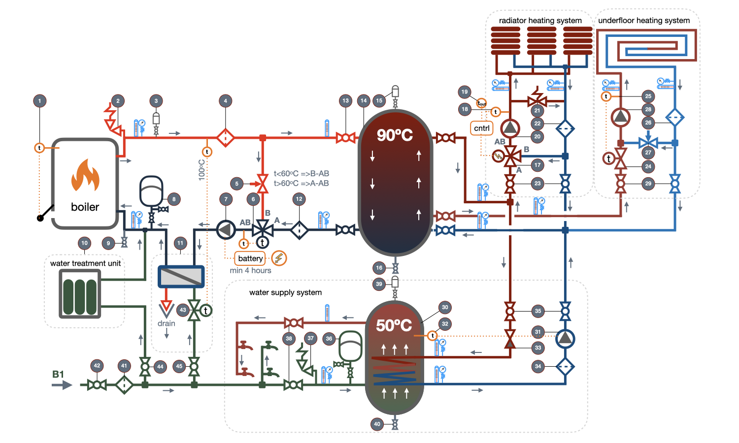
Connection diagram of the solid fuel boiler
Below is a diagram of connecting a solid fuel boiler with a thermal accumulator, three-way valve, and circulation pump to a private house heating and hot water supply system.
At first glance, the scheme seems too complicated and overloaded with unnecessary elements, but it is up to you to decide which elements to install and which not. We will explain the necessity of their use.
Many of you after reading these recommendations will understand how convenient gas fuel is, but it is unlikely that you are interested in the connection scheme of a solid fuel boiler if you still have the possibility to use gas as fuel.
We do not provide a scheme for connecting a solid fuel boiler to a heating system with natural circulation, as the boiler in such a scheme works with a significant fuel overconsumption and in unfavorable modes. We consider it expedient to use a scheme with natural circulation in modern heating systems only in the absence of power supply to the facility or in case of strict budget constraints for arranging the boiler room.
Before planning the connection scheme of a solid fuel boiler, the following peculiarities must be taken into account:
1 A solid fuel boiler is a piece of metal with significant thermal inertia, filled with hot water that cannot be instantaneously heated or cooled, melted or extinguished. Do not allow the heat supply to be stopped until the boiler is completely cooled.
2 In 99% of solid fuel boilers available on the market, there is no automation of protection and regulation, so if safety, long-term operation, and efficient fuel combustion are important to you, you will have to solve these issues when choosing the boiler connection scheme.
3 The power of the boiler may vary depending on the phase of the combustion process, both in a larger and smaller direction relative to nominal values. Therefore, it is recommended to use a solid fuel boiler together with a thermal accumulator. The thermal accumulator will provide the optimal operating mode of the boiler with maximum efficiency and also allow reducing the number of fuel loads.
4 The only safe and efficient operating mode of the boiler is the maximum power mode, in which the water temperature is maintained at 85-90°C at the boiler outlet and 65-70°C at the inlet. With such a mode, one fuel load is enough for no more than 4 hours of operation.
5 A solid fuel boiler, like any other, should operate on prepared technical water without salts of hardness, which precipitate as scale. Therefore, direct heating of tap water in the boiler is not allowed, and feeding the boiler with tap water is also not recommended.
6 There must always be circulation of the heat carrier through the working/heated boiler, regardless of whether the boiler is installed in a heating system with natural circulation or with a circulation pump.
Description of the elements of the solid fuel boiler connection diagram
[1] Draught regulator - automatically adjusts the airflow into the combustion chamber when the water temperature at the boiler outlet deviates from the set value. Stabilizes the combustion process and protects the boiler and the connected system from overheating.
[2] Safety valve of the boiler circuit - protects the boiler and the boiler circuit from exceeding the maximum allowable pressure. Important! There should be no shut-off valves, regulators, filters, or check valves on the pipeline section from the boiler outlet pipe to the safety valve installation location.
The safety valve should only operate in emergency situations.
The water discharge should be directed to a drainage channel or sewage system that can handle water with high temperature.
[3] Automatic air vent valve - automatically removes air during system filling, as well as dissolved oxygen that is released during water heating. The air vent valve should be installed at the highest point on the pipeline of the heated water outlet from the boiler.
[4] Mesh filter of the boiler circuit - designed to collect scale that forms in the boiler during water heating. Protects the circulation pump and regulating valve.
[5] Manual balancing valve - designed for hydraulic balancing of the circuit that passes through the bridge to the outlet [B] of the three-way valve and the circuit that passes through the thermal accumulator to the inlet [A] of the valve. The pressure drop in both circuits should be equal; otherwise, the water flow passing through the boiler may fluctuate significantly.
[6] Thermostatic three-way valve - protects the boiler from water entering it with a temperature below 60°C during system heating. When the water temperature is below 60°C, the three-way valve opens the flow through pipes [B-AB], and the heated water in the boiler returns back through the bypass pipe via a small circulation loop. When the temperature at the boiler outlet exceeds 60°C, the valve gradually opens pipe [A-AB], and cold water from the thermal accumulator is added to the hot water coming out of pipe [B-AB]. The thermal accumulator then begins to charge. Without the three-way valve in the circuit, the boiler may operate for a long time with the inlet water temperature below 60°C, which can cause condensation of combustion products on the surfaces of the firebox and, as a result, rapid failure of the boiler.
[7] Boiler circuit circulation pump - necessary to maintain circulation through the solid fuel boiler. The pump must operate throughout the boiler's operation, from the moment of ignition until full cooling. Even short-term stops of the pump are not allowed to avoid overheating of the boiler. Therefore, it is recommended to connect the boiler circuit circulation pump through an uninterruptible power supply (UPS) with a battery to ensure the pump's operation for at least 4 hours after a single fuel loading burnout.
[8] Expansion tank for the boiler circuit is necessary to compensate for the temperature expansion of water that occurs during heating. When calculating the expansion tank, it is necessary to take into account the entire volume of water in the closed circuit of the heating system, including the volume of water in the heat storage tank. It is fundamentally wrong to assume that the pressure in the boiler circuit will increase when the water expands, and the safety valve will work, releasing excess water volume. In this case, the system will have to be replenished every time it cools down. The expansion tank circuit must have shut-off and drainage valves necessary to adjust the pressure in the expansion tank. The ball valve installed on the branch from the boiler circuit to the expansion tank must be protected from accidental closing, preferably by removing the lever after adjusting the pressure.
[9] Drain valve is used to empty the system and, in the absence of a stationary supply line, also to fill and replenish it. The valve must be installed at the lowest point of the boiler circuit.
[10] Water treatment unit - necessary for softening hard tap water. Distilled water, which is free from hardness salts that precipitate during heating and form scale deposits, is the ideal heat transfer medium. Scale deposits in the boiler significantly reduce heat transfer through the walls of the heat exchanger and can lead to overheating and failure of the boiler.
[11] Boiler overheat protection unit - is mandatory in European countries.
The essence of the unit is that if the hot water tank is filled with water at a temperature of 90°C, and the fuel in the combustion chamber is not completely burned, heat transfer practically stops and the boiler begins to overheat the water above the maximum allowable temperature, which can lead to a breakdown and failure of the boiler. Even full closure of the draft regulator will not immediately cool down the chamber and boiler.
The overheat protection unit consists of a high-speed heat exchanger, to the heating chamber of which cold tap water is connected, and to the cooling - the circulating water of the boiler circuit before entering the boiler. A direct-acting temperature regulator [43] is installed on the supply of cooling tap water, which will open the supply of tap water only if the temperature of the water at the outlet of the boiler exceeds the maximum permissible mark of 95°C.
As soon as the water at the outlet of the boiler exceeds 100°C, the regulator will open the supply of cold water, which will cool the overheated water in the return pipeline through the walls of the heat exchanger, which is supplied to the boiler.
It is recommended to maintain the pressure at the point of connection of the water supply to the overheat protection unit even in the absence of electricity.
The system must be configured and the heat exchanger must be calculated in such a way as to cool the overheated water from 90 to 65°C (not lower, as too cold water cannot be supplied to a heated boiler).
The tap water that has come out of the heat exchanger is discharged to a drainage well or sewage system that allows for the discharge of hot water.
[12] Mesh filter - necessary for protecting the three-way valve and pump of the boiler circuit from sludge particles that may enter from the thermal accumulator.
[13] Shut-off valves of the thermal accumulator - used to disconnect the thermal accumulator from the boiler circuit and heating system circuits. The presence of shut-off valves allows water to be retained in the thermal accumulator during repair and maintenance work on the equipment.
[14] Thermal accumulator - used for collecting, storing, and distributing heat from the thermal accumulator. The boiler operates at maximum efficiency only at nominal load, and the heating system load varies depending on the outside air temperature, and the demand for hot water depends on the time and amount of water consumption.
The thermal accumulator creates an optimal operating mode for the boiler and stores heat for further use in heat recovery systems. In addition, by operating with maximum boiler efficiency in a system with a thermal accumulator, fuel costs are reduced by 20-30%, and the service life of the boiler is increased.
It is recommended to choose a thermal accumulator so that its capacity is sufficient for accumulating heat released during the complete combustion of full fuel load. Thus, in a system with a thermal accumulator, you can heat the boiler in the evening and use the heat on the next day, in the morning or even the following day. Therefore, in systems with a conventional steel or cast iron boiler and thermal accumulator, there is no need to use expensive long-burning pyrolysis boilers.
[15] Automatic air vent of the thermal accumulator - installed on the upper pipe of the tank or on the pipeline connected to the upper pipe of the tank. It removes air during tank filling, as well as if air bubbles enter the tank with the flow of the heat transfer fluid.
[16] Drain valve of the thermal accumulator - necessary for emptying the thermal accumulator.
[17] Three-way valve for the radiator heating circuit. Since water in the thermal accumulator can be stored at a temperature of 90°C, and for the radiator heating system, such water temperature may be required only at the lowest outside temperature, the three-way valve maintains the temperature of the water entering the heating system according to the required temperature at the actual outside temperature. The necessary temperature is obtained by mixing two streams of water, one of which is taken from the accumulator tank, and the other from the bypass in the return pipeline.
A three-way valve is installed in the radiator heating circuit together with a temperature controller, an outdoor temperature sensor [19], and a heat carrier temperature sensor [18].
[20] Circulation pump for the radiator heating circuit. When heat extraction from the thermal accumulator is cut off by the three-way valve, water in the system continues to circulate through the [B-AB] port of the three-way valve. If the circulation pump is equipped with a rotation frequency regulator, the bypass valve [21] on the diagram may not be installed.
[21] Bypass valve for the radiator heating circuit is installed if thermostatic valves are planned to be installed on radiators in the heating system. Since it is possible that thermostatic valves on all radiators can be closed, the circulation in the system will also stop, while the pump will actually work with zero flow rate, which can lead to its failure.
When the thermostatic valves on the radiators are closed, the pressure at the connection point of the bypass valve will increase and it will open, providing pump operation through the small circuit bypassing the heating system.
[22] Mesh filter for the radiator heating circuit, protects the boiler circuit from sludge that may enter from the heating system.
[23] Main valves for the radiator heating system are necessary to enable complete disconnection of the system for revision or other purposes.
[24] Direct-acting temperature controller of the underfloor heating system - maintains the desired temperature at the entrance to the warm floor using a complete temperature sensor [25]. Typically, the temperature in the supply of warm floors is 30-35°C.
The temperature controller determines the amount of water taken from the heat accumulator and the amount of water added from the return pipeline. With complete closure of the selection from the heat accumulator, all water entering the underfloor heating system will be taken from the return pipeline.
[26] Circulation pump of the underfloor heating system maintains the circulation of water through the warm floor.
[27] Balancing valve of the underfloor heating circuit is needed for the hydraulic balancing of the bypass and the supply line. The hydraulic resistance of the balancing valve should be equal to the resistance of the temperature controller.
[28] Mesh filter of the underfloor heating system protects the boiler circuit from dirt that may enter from the underfloor heating circuit.
[29] Shut-off valves of the semi-underfloor heating system are necessary for complete disconnection of the circuit for maintenance or other reasons.
[30] Hot water storage tank for hot water supply system. In the hot water storage tank, water for the hot water supply system is heated by the hot water coming from the thermal accumulator through the built-in coil.
Important! In residential buildings, use hot water storage tanks with built-in heating coils. It is strongly not recommended to use thermal accumulators with built-in coils inside which the water is heated, as the water in the thermal accumulator can reach 90°C, and, accordingly, it will heat the stagnant water for the hot water supply system (HWSS) to the same temperature if there is no water intake in the coil.
[31] Circulation pump of the hot water storage tank loading circuit is activated by the temperature relay sensor [32], installed in the tank. As soon as the water being heated in the tank reaches the set temperature, the relay will turn off the pump power and the circulation of the heating water will stop.
[33] Check valve prevents the circulation of the coolant when the pump power is off.
[34] Mesh filter protects the pump from sludge that has settled on the pipes of the hot water storage tank.
[35] Heating circuit shut-off valve of the water heating unit for the hot water supply system is necessary for completely disconnecting the unit from the boiler circuit.
[36] Hydroaccumulator (expansion tank) accepts the excess volume of water that is formed during thermal expansion of the water supply which is being heated. The requirements for installing a hydroaccumulator are the same as the requirements for installing an expansion tank in a boiler circuit [8].
[37] Safety valve of the water heater protects the tank and the hot water supply system from exceeding the calculated pressure. In this case, the pressure may exceed the calculated pressure when the water taps are closed and the water is heated in a closed circuit of the water heater.
[38] Shut-off valve of the hot water supply heating circuit disconnects the water heater from the hot water supply system.
[39] Automatic air vent valve of the water heater will release the dissolved oxygen that is released from the water supply during its heating. The air vent valve should be installed on the top nozzle of the water heater or at the highest point of the pipeline connected to it.
[40] Drain valve of the water heater is necessary for emptying the tank.
[41] Mesh filter protects the boiler room from mechanical impurities that enter along with the water flow.


 Heating and domestic hot water systems for dwellings
question : comment : feedback
738
 Catalog of
