Please do not block ads on our site. Clicks on ads help us exist, grow and become more useful for you!
Schemes of the heating substation for the heating system
Dependent scheme with two-way valve and pumps in the supply pipeline
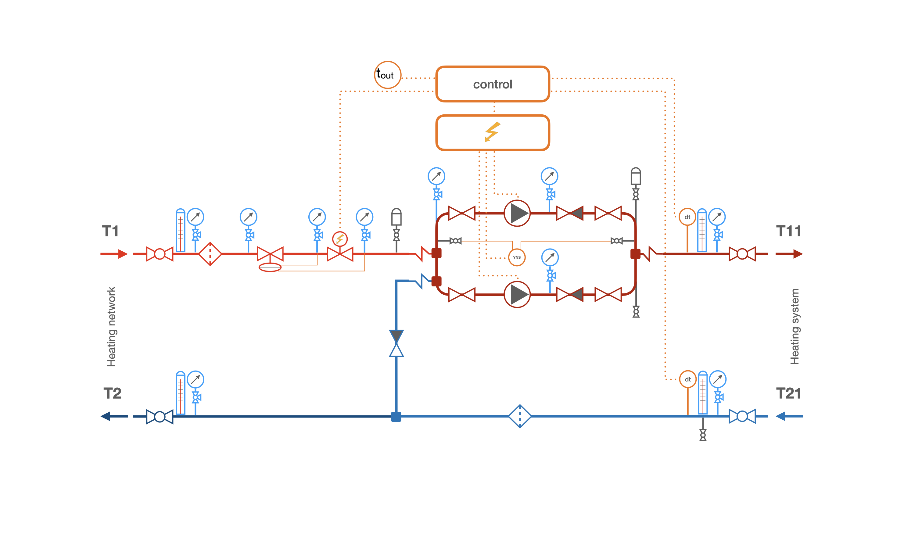
The dependent scheme of connecting the heating system heating substations to the heat network with a two-way valve of the heat flow controller and circulation-mixing pumps in the supply pipeline of the heating system.
The scheme is used if:
1 The calculated temperature graph of the heat source exceeds the calculated temperature graph of the heating system (for example, at the input of the heat network it is 120/70, and in the heating system it is necessary to maintain 90/70).
2 The working pressure in the return pipeline of the heat network and the static pressure in the heat network exceed the static pressure of the heating system by at least 0.5 bar. The static pressure of the heating system corresponds to the height of the water column in meters from the location of the heating substations to the highest point of the heating system. The pressure unit converter allows you to convert the input data provided by the heat supply organization in other units of measurement (bar, MPa or kgf/cm²).
3 The pressure in the supply and return pipelines of the heat network, as well as the static pressure in the heat networks, do not exceed the maximum permissible pressure for the heating system, which is determined by the strength limit of the weakest element (radiators, pipes).
4 Automatic quality control of the heat carrier temperature depending on the outside air temperature and/or according to the daily and weekly schedule of the system operation should be implemented in the heating substations.
Description of the heating substation scheme and its operation principle:
The operation of the heating substation is controlled by a programmable controller, which is connected to a temperature sensor of outdoor air, a temperature sensor of the heating system supply water, and a two-way regulating valve with an electric drive.
The temperature graph of the heating system, which reflects the dependence of the water temperature supplied to the heating system on the outdoor air temperature, day of the week, and time of day, is entered into the controller. The controller measures the outdoor air temperature, determines the required water temperature at the inlet of the heating system, and compares it with the temperature measured by the t11 sensor. If the temperature deviation occurs, the controller sends a signal to close or open the regulating valve on the heating system supply pipeline.
The regulating valve can either fully open the supply of the heat carrier or fully close the supply pipeline. Even when the regulating valve is fully open, the addition of water from the return pipeline does not stop because the water coming from the heating system is conditionally 'overheated,' i.e., has a temperature that exceeds the required temperature for the heating system. When the supply pipeline is fully closed, all the heat carrier supplied to the heating system is taken through the jumper from the return pipeline.
< p>Regardless of the degree of closing of the regulating valve, the volume of water supplied to the heating system is stable and determined by the characteristics of the circulation pump, only the proportions of the two water flows in the mixture - the flow taken from the return pipeline and the flow from the supply pipeline - change.In case the working pump fails, the water circulation in the system will stop, so the scheme provides for two pumps - working and backup.
The pumps are connected to the electrical network through a control panel that provides the following levels of protection:
- Dry running protection
- Protection against phase voltage imbalances
- Protection against phase breaks and short circuits
- Thermal protection against increased current loads
- Automatic switching to the backup pump in case of failure of the working one
A pressure drop regulator is installed at the inlet of the heating system, which stabilizes the pressure drop, limits the maximum flow rate of the heat carrier from the heating network, and creates a regulating valve operating mode in which the stem movement smoothly changes the water flow passing through it.
To limit the maximum flow rate of the heat carrier, the pressure drop on the regulator is set to be equal to the pressure drop on the regulating valve in the fully open position at the maximum flow rate of the heat carrier.
In addition to new construction, this scheme is used in the reconstruction of a heating substations with the replacement of elevator units.
Features of the scheme
In the operating mode, the pressure in the return pipeline of the heating system is equal to the pressure in the return pipeline of the heating network at the input, and the pressure at the point of mixing flows is slightly lower than the pressure in the return pipeline of the heating network.
Even with the regulator valve on the supply pipeline fully open, cooled water from the return pipeline will be mixed into the flow entering the heating system.

Dependent scheme with a two-way valve, pumps in the supply pipeline and a balancing valve
Used in cases where the static or working pressure in the return pipeline of the heating network is lower than the static pressure of the heating system + 0.5 bar.
Pressure relief controllers is installed to protect the heating system from partial or complete draining.
Dependent scheme with a two-way valve and pumps in the return pipeline

Dependent scheme for connecting the heating system with automatic weather-dependent regulation based on a programmable controller with a two-way valve and circulation-mixing pumps in the return pipeline.
The scheme is used if:
1 The calculated temperature graph of the heat source exceeds the calculated temperature graph of the heating system.
2 The working pressure in the return pipeline of the heating network and the static pressure in the heating network exceed the static pressure of the heating system, at least by the value equal to the maximum head of the pump + 0.5 bar.
3 The pressure in the supply and return pipelines of the heating network, as well as the static pressure in the heating networks, does not exceed the maximum allowable pressure for the heating system, determined by the strength limit of the weakest element (radiators, pipes).
4 An automatic quality control of the coolant temperature is required in the heating substation depending on the outdoor air temperature and/or the daily or weekly operating schedule of the system.
5 The temperature in the supply pipeline of the heating system in operating mode may exceed the permissible temperature for the circulation pump.
Features of the scheme
The pressure in the return pipeline of the heating system will always be lower than the pressure in the return pipeline of the heating network at the building input by the head of the pump in the working point.
The pressure in the supply pipeline of the heating system will be slightly lower than the pressure in the return pipeline of the heating network.
Dependent scheme with a three-way valve and circulation pumps

Dependent scheme of connecting the heating substation of the heating system to the heat source with a three-way valve of the heat flow regulator and circulation-mixing pumps in the supply pipeline of the heating system.
This scheme is used in an individual heating substations under the following conditions:
1 The working temperature graph of the heat source (boiler room) exceeds or is equal to the temperature graph of the heating system. The heating substations connected by this scheme can work both with mixing the flow from the return pipeline and without it, that is, sending all the heat carrier from the supply pipeline of the heating system directly to the heating system.
For example, the calculated temperature graph of the heating system is 90/70°C, which is equal to the temperature graph of the heat source, but the heat source always operates at a temperature of 90°C regardless of external factors, and it is necessary to send the heat carrier with a temperature of 90°C to the heating system only at the calculated outdoor air temperature (for Kyiv -22°C). Thus, in the heating substations, cooled heat carrier from the return pipeline will be added to the water from the source until the outdoor air temperature drops to the calculated value.
2 The heating substations is connected to an unpressurized collector, hydraulic arrow, or heat pipeline with a pressure difference between the supply and return pipeline not exceeding 0.3 bar.
3 The pressure in the return pipeline of the heat source in both static and dynamic modes should exceed the height from the connection point of the heating substations to the highest point of the heating system (building statics) by at least 0.5 bar.
4 The pressure in the supply and return pipelines of the heat source, as well as the static pressure in the heating pipelines, should not exceed the maximum permissible pressure for the heating system of the building connected to this District heating substation.
5 The heating substations connection scheme should provide automatic quality control of the heating system based on a temperature or time graph.
Description of the operation of the District heating substation with a three-way valve
The principle of operation of this scheme is similar to the first scheme, except that the three-way valve can completely shut off the return flow, in which case all the heat transfer fluid coming from the heat source without mixing will be supplied to the heating system.
In the case of complete closure of the supply pipe of the heat source, as in the first scheme, only the heat transfer fluid that is taken from the return pipe will be supplied to the heating system.

Dependent scheme with a three-way valve, circulation pumps and pressure differential regulator.
It is used when the pressure drop at the connection point of the District heating substation to the heating network is more than 0.3 bar. In this case, a pressure differential regulator is selected to throttle and stabilize the excess pressure difference at the input.
Independent scheme of the District heating substation
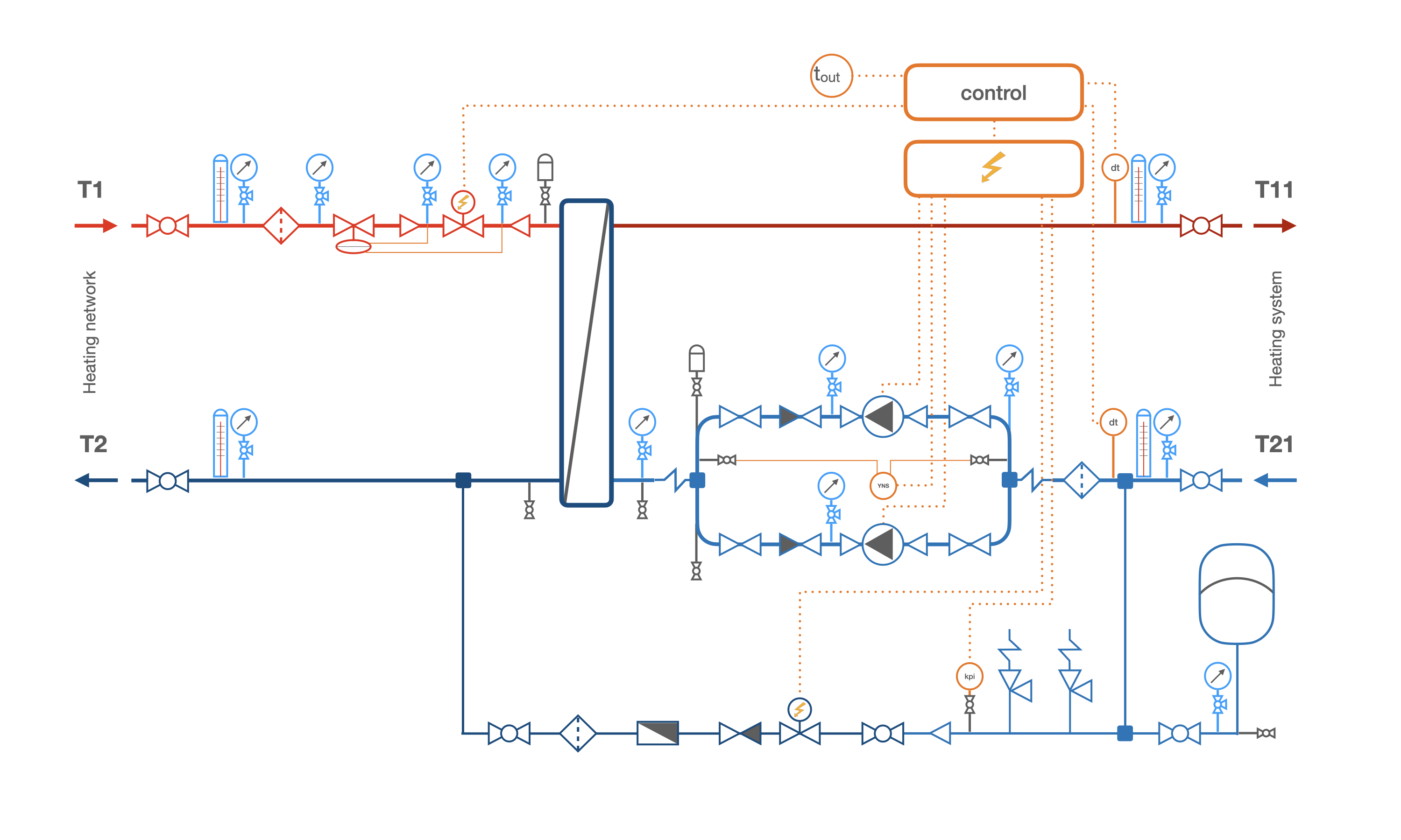
The independent scheme of the District heating substation with a two-way valve, pressure differential regulator, circulation pumps, closed expansion tank and automated filling and feeding line.
The independent connection scheme of heating substations is used in the following cases:
1 The static pressure and/or pressure in the supply and/or return pipeline of the heating network exceeds the permissible pressure in the heating system.
2 The temperature curve of the heat source exceeds the temperature curve of the heating system. For example, the temperature curve of the heat source is 110/70, while in the heating system it is 90/70.
3 The building has 12 or more floors.
4 The pressure difference at the input of the heating network exceeds 0.4 bar (subject to the conditions of overcoming the hydraulic resistance of the heat exchanger and control valves).
5 The independent connection scheme is mandatory according to the technical conditions of the heat supply organization or the technical task of the customer.
Principle of operation of a heat unit connected by an independent scheme
The hot heat transfer fluid coming from the heat source enters the plate heat exchanger where it cools down and heats up the water circulating in the heating system.
The use of a plate heat exchanger protects the heating system from changes in the hydraulic regime of the heat source / district heating network, making it independent.
In contrast to dependent schemes where water taken from the district heating network enters the heating system, in the case of an independent connection of the heat unit, water from external networks enters the system only once during filling and in small quantities during replenishment to compensate for leaks of heat transfer fluid in the system. Independent connection of the heating system reduces the impact on pipes and heating system elements not trapped by filters.
The electronic controller equipped with an ambient air temperature sensor and a heat transfer fluid temperature sensor that enters the heating system controls the heat unit. The controller is also connected to the actuator of the regulating valve installed on the supply pipeline of the heat source.
The controller has a dependency of the temperature of the water supplied to the heating system on the temperature of the outside air, which it periodically checks. If the controller detects that the heat transfer fluid is entering the heating system with insufficient temperature, it sends an opening signal to the regulating valve on the supply pipeline of the district heating network, and when the temperature exceeds the set value, the controller closes the valve until the supply is completely shut off.
The heat transfer fluid flow rate restriction is implemented based on a pressure drop regulator, as in the first scheme (see above).
The circulation of the heat transfer fluid in the heating system is created by two silent pumps, one of which is backup. The pair of circulation pumps is equipped with an automation shield with a list of functions described in the description of the first scheme.
Water expands in volume when heated and contracts when cooled. Since water is practically incompressible, when heated in a closed circuit of the heating system, the pressure will rise sharply, which will lead to the destruction of the weakest element of the heating system.
To avoid the destructive effects of heated water in a closed heating system, an expansion tank is added to the system, designed to accommodate the increase in volume of the heated fluid. The expansion tank is divided into two parts by an elastic membrane, which can stretch to accommodate all the increased volume of heated water, and contract when the temperature of the water in the heating system decreases, pushing back the previously received volume of water back into the system.
To protect the heating system from accidental pressure buildup, at least two safety valves are installed in it, one of which is a reserve.
The heating system is replenished by an pressure regulator in automatic mode, as soon as the pressure in the heating circuit drops below the regulator's set pressure.
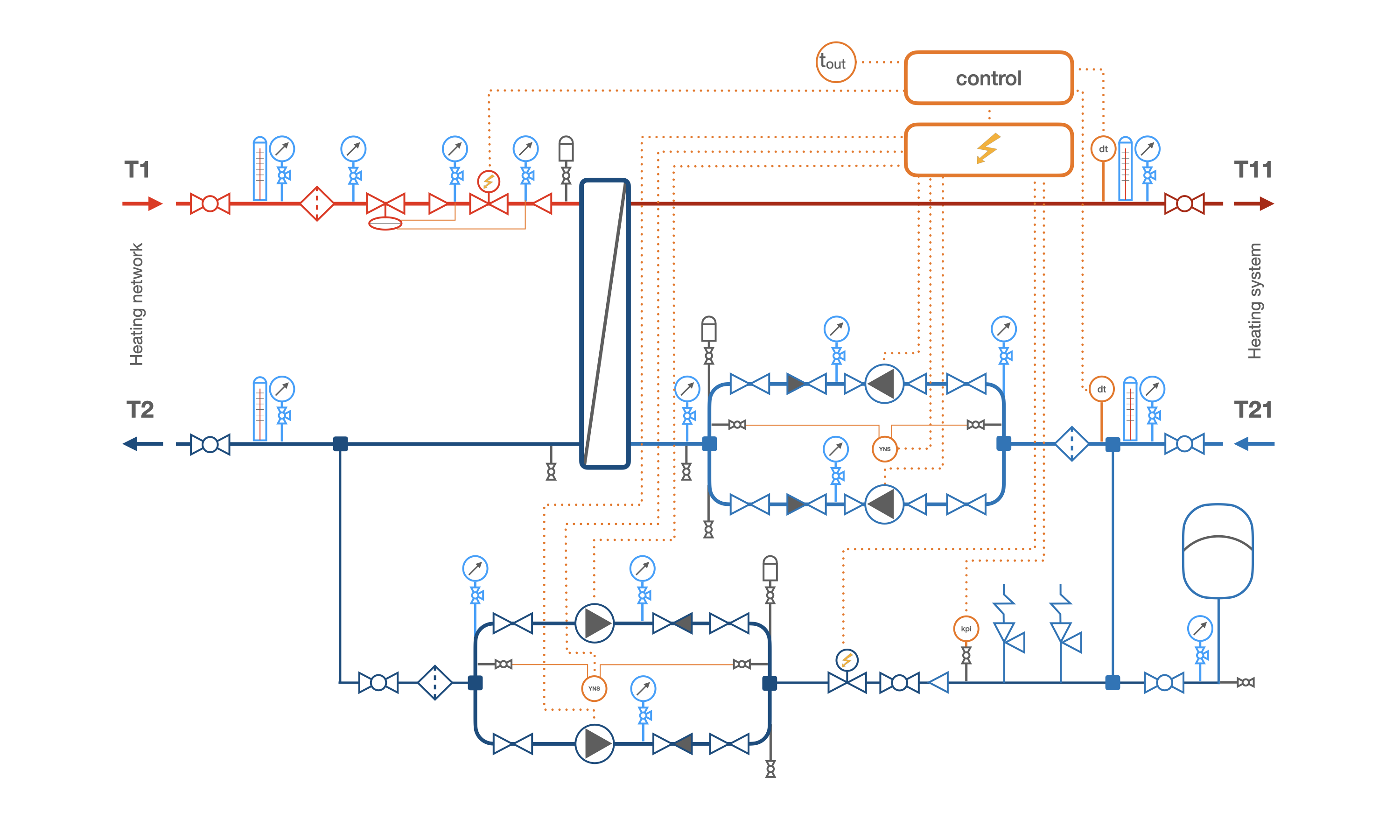
Independent heating unit scheme with a block of booster pumps
This scheme is used when the pressure in the supply pipeline at the heat source inlet is lower than the static pressure of the heating system. The scheme is not mandatory, but it is recommended to use it if the pressure in the return pipeline of the heating network or the static pressure of the heat source is lower than the static pressure of the heating system.


 Tutorial Herz
question : comment : feedback
1043
 Catalog of
 OTOS

