Please do not block ads on our site. Clicks on ads help us exist, grow and become more useful for you!
Diagrams of connecting buffer storage tank
The connection scheme of a buffer storage tank depends on the thermal and hydraulic regimes of the heat source and heat consumers, as well as on the number of sources and consumers.
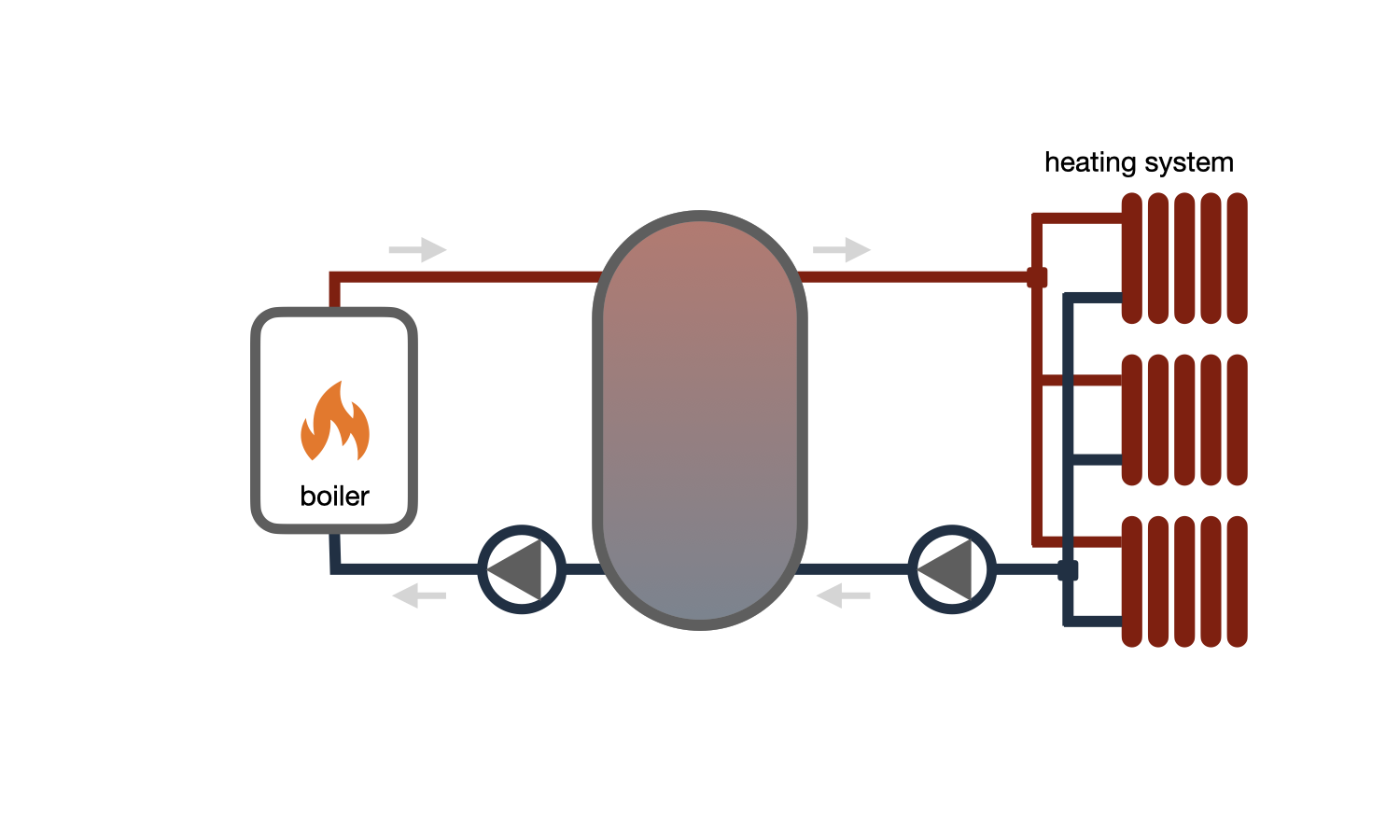
The direct connection scheme of the buffer storage tank to the heat source and heat consumer circuit is used if:
- The requirements for the quality of the heat carrier in the heat source and heat consumer circuit are the same.
- The operating pressure in the heat consumer (at all modes) does not exceed the maximum allowable pressure for the heat source and the buffer storage tank itself.
- The temperature of the heat carrier in the buffer storage tank at all modes corresponds to the necessary temperature for the consumer.
This scheme is used in small heating systems of private houses with quantitative regulation on heating appliances. In this case, a constant temperature is maintained at the outlet of the heat source and, accordingly, in the buffer storage tank.
If the thermal regime of the consumer involves qualitative regulation with different temperature of the heat carrier supply depending on the time of day or the temperature of the outside air, this scheme is supplemented with a mixing module.
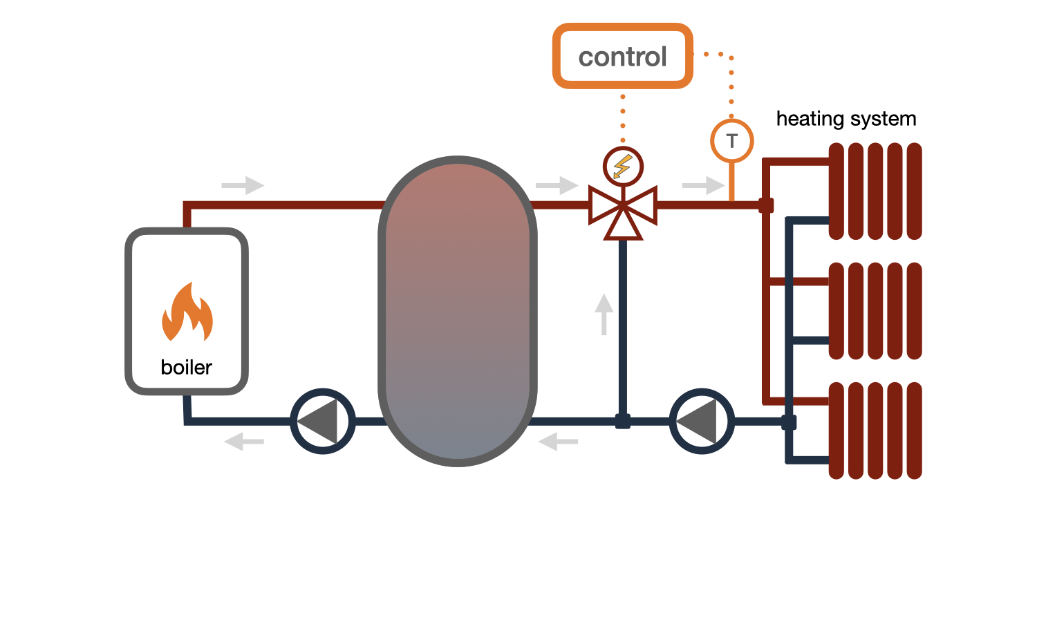
The connection scheme of the consumer to the buffer storage tank with a mixing module is used if:
- The requirements for the quality of the heat carrier in the heat source and heat consumer circuit are the same.
- The temperature of the heat carrier at the outlet of the heat source exceeds the temperature necessary for the consumer on one of the modes.
- The operating pressure in the heat consumer (at all modes) does not exceed the maximum allowable pressure for the heat source and the buffer storage tank itself.
This scheme is used in heating systems with qualitative regulation, where the temperature of the heat carrier entering the heating system depends on the temperature of the outside air, time of day, day of the week, or the temperature of the air in the control room.
A three-way valve adds heat carrier from the return pipeline in the necessary proportion to the hot heat carrier taken from the top of the buffer storage tank to obtain the desired temperature of the mixture that enters the heating system.
The ability to maintain a maximum high water temperature in the buffer storage tank is one of the advantages of this scheme, as it allows increasing its storage capacity.
If the operating pressure in the heat consumer exceeds the operating pressure for the buffer storage tank or heat source, an independent connection of the consumer is used (via a heat exchanger).
If the operating pressure in the heat source circuit exceeds the allowable pressure for the buffer storage tank or heating system, a scheme with a heat exchanger in the heat source circuit is used.
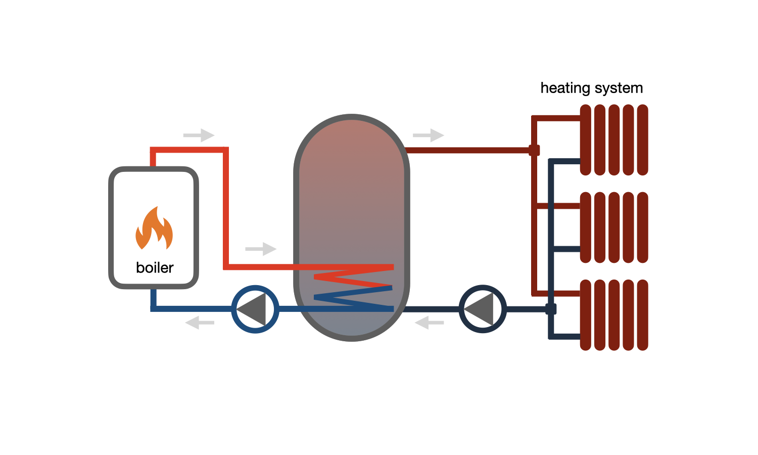
The connection diagram of a buffer storage tank with a built-in heat exchanger is used if:
- The working pressure in the heat source circuit exceeds the allowable pressure for the heating system.
- There are different requirements for the quality of the heat carrier in the heat source and the heat consumer circuit.
If the surface area of the heat exchangers built into the buffer storage tanks is insufficient to heat the required volume of water in the given time, schemes with an external heat exchanger and loading pump are used.

The connection diagram of a buffer storage tank with an external heat exchanger and loading pump is used if:
- The heat exchangers built into the system cannot heat the tank within the required time.
- The pressure of the heat carrier in the heat source circuit exceeds the allowable pressure for the heat consumer or the buffer storage tank.
- There are different requirements for the quality of the heat carrier in the heat consumer and heat source circuits.
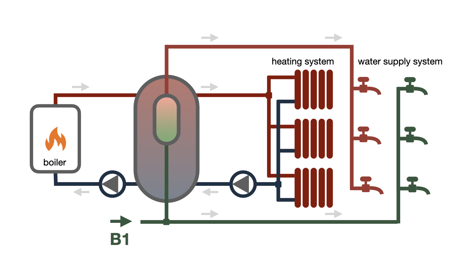
Buffer storage tanks with a built-in domestic hot water tank are used for connecting systems of hot water supply with short but high peak water demand.
Such buffer storage tanks differ in their ability to provide high peak demand for hot water for a short period of time, but after the built-in tank is filled with cold water, reheating will take a long time.
For systems with a high demand for long-term heating power, buffer storage tanks with built-in or external heat exchangers for hot water supply systems are installed.

The connection scheme of a buffer storage tank with a built-in heat exchanger for hot water supply is used when high long-term power is required for heating hot water.
Buffer storage tanks with a built-in heat exchanger for hot water supply provide high long-term power, but cannot cover peak loads beyond it.
If the required long-term water heating power is not provided by serially installed heat exchangers, a buffer storage tank with an external heat exchanger and a loading pump is used.

The bivalent connection scheme of the buffer storage tank with a solar collector. The solar collector is connected to the buffer storage tank through a built-in heat exchanger located at the bottom of the tank. In this case, the operation is provided in the mode of maximum possible heating of the tank by solar energy, and if necessary, additional heating is carried out by another source.
In this scheme, the additional source can be a gas, solid fuel or electric boiler.
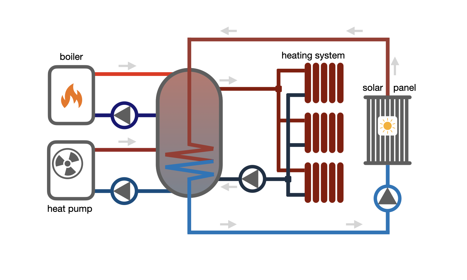
Connection of a consumer through a buffer storage tank from multiple heat sources. The use of several heat sources in modern systems is due to the different cost of one unit of heat energy obtained from each of them.
Heat obtained from the sun has the lowest cost, but it is not always available, and its peaks of receipt do not usually coincide with peak consumption.
Heat obtained from a heat pump is somewhat more expensive than solar energy, but it can be obtained at all times, but significant capital costs are required to cover the entire heat capacity of the consumer through it, so the heat pump capacity is usually lower than the required system capacity.
Heat obtained from a gas, electric or solid fuel boiler is the most expensive, so it is used only for additional heating in case of insufficient power of the first two sources.
The buffer storage tank allows accumulating thermal energy from several sources and using it for one or several consumers. Low-temperature sources, such as a heat pump and a solar collector, are connected to the bottom of the tank, and high-temperature sources, such as a solid fuel, gas, or electric boiler, to the top.


 Heating and domestic hot water systems for dwellings
question : comment : feedback
1302
 Catalog of
 Buffer storage tanks
Viessmann
Viessmann
Viessmann
Viessmann
Viessmann
Elbi
Теплобак
Теплобак
Теплобак
Теплобак
Zani
Zani
Zani
Flamco
Flamco
Flamco
Flamco
Huch
Huch
Wolf
Wolf
Wolf
Reflex
Reflex
Reflex
Rehau
Bosch
Bosch
Huch
Vaillant
Vaillant
Zani

