Please do not block ads on our site. Clicks on ads help us exist, grow and become more useful for you!
How to install a check valve
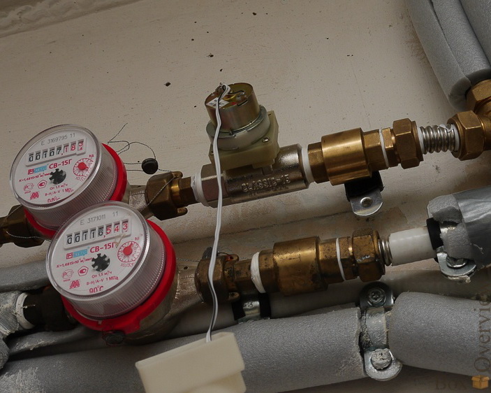
Threaded check valves are divided into spring-loaded and non-spring-loaded. Spring-loaded check valves can be installed in any position, while non-spring-loaded valves are installed on vertical pipelines with flow from bottom to top or on horizontal pipelines.
It is recommended to install a mesh filter before the check valve to protect against abrasive substances in the flow.
The body of the check valve should not be subjected to bending, rotation, tension, or compression loads from the connected pipeline.
The check valve allows flow only in one direction, and the working flow direction is indicated by an arrow on the valve body - ensure correct installation according to the technological scheme.
Do not damage the paint coating on the valve body, as in addition to its decorative function, it also protects the valve from corrosion.
Thread joint packing sequence
1. Take a bundle of flax fiber with enough threads so that in a twisted state its diameter is approximately equal to the depth of the thread. The length of the bundle should provide 1.5-2 times the number of windings as the number of thread turns.
2. Step back about 50-70 mm from the beginning of the bundle, twist it slightly, place it in the first thread turn, and, holding it by hand, tightly wind the long branch of the bundle clockwise, placing it in each thread turn.
3. After reaching the end of the thread, continue winding with a second layer, moving the windings to the start of the thread. The length of the second layer should be about 2/3 of the thread length.
4. Wind the left end of the bundle (50-70 mm) similarly clockwise, from the end of the thread to its start.
5. Apply a layer of sealant on the surface of the packing.
6. Tighten the connecting elements by hand. With proper packing, the mounted element should tighten by 1.5-2 turns.
7. Use a wrench or torque wrench to continue tightening the element. If the mounted element needs to be positioned in a specific orientation, finish tightening it in the required position.
With proper packing, during tightening, the effort should not exceed the torque specified below:
| DN15 | DN20 | DN25 | DN32 | DN40 | DN50 | DN65 | DN80 | DN100 |
|---|---|---|---|---|---|---|---|---|
| 70 Nm | 95 Nm | 120 Nm | 150 Nm | 190 Nm | 230 Nm | 280 Nm | 350 Nm | 400 Nm |


question : comment : feedback
220
 Catalog of
