Please do not block ads on our site. Clicks on ads help us exist, grow and become more useful for you!
Installation of a direct-acting temperature regulator
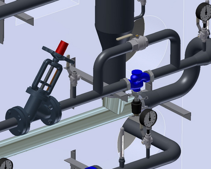
Installation of a direct acting temperature regulator should be carried out in accordance with the installation instructions, and the following should also be taken into account:
- The mounting position should be selected on a horizontal pipeline with the thermostatic actuator downwards, unless otherwise stated in the installation instructions.
- Before the temperature regulator, it is recommended to have a straight section of pipeline of at least 5DN, and after it, of at least 10DN. Otherwise, the flow capacity may differ from the nominal values.
- The installation of the temperature regulator should exclude any bending, twisting, compression or stretching forces from the connected pipelines.
- Pressure gauges should be installed before and after the regulator, and a control thermometer should be installed at the temperature sensor location. It should be noted that tapping a thermometer into a pipeline DN50 and smaller without an expansion device is not allowed.
- A strainer should be installed before the regulator in the direction of water flow.
Sequence for packing a threaded connection
1. Take a flax fiber string with enough threads so that its twisted diameter is approximately equal to the depth of the thread. The length of the string should provide for 1.5-2 times more windings than the number of thread turns.
2. Starting approximately 50-70 mm from the beginning of the string, slightly twist it, place it in the first thread turn, and, holding it with your hand, tightly wind a long branch of the string clockwise, placing it in each thread turn.
3. When reaching the end of the thread, continue winding with a second layer, shifting the turns to the beginning of the thread. The length of the second layer winding should be approximately equal to 2/3 of the thread length.
4. Wind the remaining end of the string (50-70 mm) similarly clockwise, from the end of the thread to its beginning.
5. Apply a layer of sealant to the winding surface.
6. Tighten the connecting elements by hand. With correct packing, the assembled element should turn 1.5-2 full rotations.
7. Continue tightening the element with a wrench or a torque wrench. In case the assembled element needs to be in a specific position, complete tightening it in the necessary position of the element.
With proper packing, during tightening, the force should not exceed the tightening torque listed below:
| DN15 | DN20 | DN25 | DN32 | DN40 | DN50 | DN65 | DN80 | DN100 |
|---|---|---|---|---|---|---|---|---|
| 70 Nm | 95 Nm | 120 Nm | 150 Nm | 190 Nm | 230 Nm | 280 Nm | 350 Nm | 400 Nm |
Tightening torques for flange connections
| DN | Nut/Bolt | Torque, Nm |
|---|---|---|
| 15 - 32 | М 10 | 15 - 30 |
| 40 - 65 | М 12 | 35 - 50 |
| 80 - 100 | М 16 | 75 - 100 |
| 125 - 150 | М 16 | 80 - 120 |
| 200 | М 20 | 150 - 200 |
| 250 - 400 | М 24 | 340 - 410 |
| 500 | М 27 | 340 - 410 |


 EN 1092-1
question : comment : feedback
168
 Catalog of
 temperature controllers
Danfoss
Danfoss
Danfoss
Danfoss
Danfoss
ARI Armaturen
ARI Armaturen
ARI Armaturen
ARI Armaturen
Samson
Samson
Samson
Samson
Samson
Termen
Termen
LDM

