Please do not block ads on our site. Clicks on ads help us exist, grow and become more useful for you!
Installation of a water pressure regulator
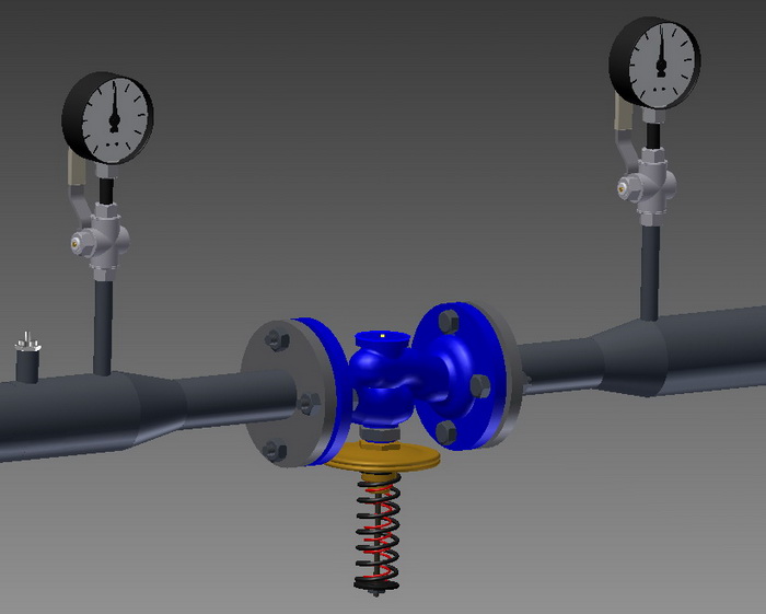
- The pressure regulator should be installed on a horizontal pipeline with the membrane chamber downwards, unless otherwise specified in the project or manufacturer's instructions.
- The pressure regulator should not be subjected to twisting, stretching or compression loads from connected pipelines.
- The flow direction should coincide with the direction of the arrow on the regulator valve.
- Different manufacturers provide different data, but on average when installing a pressure regulator, it is recommended to observe straight sections of 5DN before and 10DN after it.
- Manometers should be installed before and after the regulator.
- A mesh filter should be installed before the pressure regulator in the direction of the coolant flow.
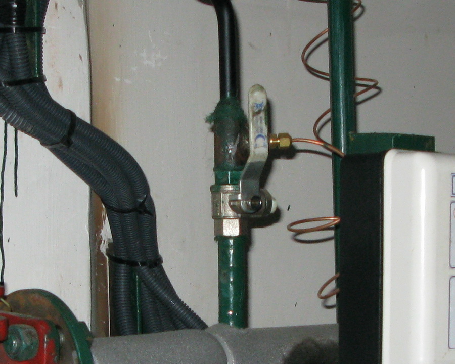
- The connection of the impulse tube of the pressure regulator should be made through a valve for blowing and preventive maintenance, if not prohibited by the manufacturer's instructions.
- Some manufacturers recommend maintaining a distance of at least 5DN between the impulse sampling point and the regulating valve.
- For the installation of the regulator on a pipeline transporting water with high temperature, an impulse cooler and a stem cooler may be required.
- If the failure of the regulator can cause an emergency situation, a safety valve should be installed in the pressure maintenance area.
Sequence for packing a threaded connection
1. Take a flax fiber string with enough threads so that its twisted diameter is approximately equal to the depth of the thread. The length of the string should provide for 1.5-2 times more windings than the number of thread turns.
2. Starting approximately 50-70 mm from the beginning of the string, slightly twist it, place it in the first thread turn, and, holding it with your hand, tightly wind a long branch of the string clockwise, placing it in each thread turn.
3. When reaching the end of the thread, continue winding with a second layer, shifting the turns to the beginning of the thread. The length of the second layer winding should be approximately equal to 2/3 of the thread length.
4. Wind the remaining end of the string (50-70 mm) similarly clockwise, from the end of the thread to its beginning.
5. Apply a layer of sealant to the winding surface.
6. Tighten the connecting elements by hand. With correct packing, the assembled element should turn 1.5-2 full rotations.
7. Continue tightening the element with a wrench or a torque wrench. In case the assembled element needs to be in a specific position, complete tightening it in the necessary position of the element.
With proper packing, during tightening, the force should not exceed the tightening torque listed below:
| DN15 | DN20 | DN25 | DN32 | DN40 | DN50 | DN65 | DN80 | DN100 |
|---|---|---|---|---|---|---|---|---|
| 70 Nm | 95 Nm | 120 Nm | 150 Nm | 190 Nm | 230 Nm | 280 Nm | 350 Nm | 400 Nm |
Tightening torques for flange connections
| DN | Nut/Bolt | Torque, Nm |
|---|---|---|
| 15 - 32 | М 10 | 15 - 30 |
| 40 - 65 | М 12 | 35 - 50 |
| 80 - 100 | М 16 | 75 - 100 |
| 125 - 150 | М 16 | 80 - 120 |
| 200 | М 20 | 150 - 200 |
| 250 - 400 | М 24 | 340 - 410 |
| 500 | М 27 | 340 - 410 |


 EN 1092-1
question : comment : feedback
214
 Catalog of
 pressure reduction controllers
Danfoss
Danfoss
Danfoss
Gestra
Samson
Samson
Samson
Honeywell - Resideo
LDM
LDM
ARI Armaturen
КПСР Групп
IMI Hydronic
IMI Hydronic
Samson
RTK
RTK
Termen
Termen

