Please do not block ads on our site. Clicks on ads help us exist, grow and become more useful for you!
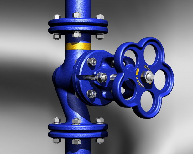
Installation of globe valve
Installation Recommendations
The globe valves can be installed in any mounting position on a vertical or horizontal pipeline, except with the stem facing downwards.
The globe valve is unidirectional, so the direction of the flow of the working medium should coincide with the arrow on the body. The working medium is supplied under the valve. The globe valve should not be used in reverse mode, otherwise, during long-term use, this can lead to valve breakage.
Globe valves with electric actuators are installed with the stem facing vertically upwards, if another position is not provided by the installation instructions. If installed in the open air above the electric drive, a shelter should be arranged.
Protection of the Body from Bending Stress
The globe valve body should not experience bending, twisting, stretching, or compression stress from connected pipelines, especially for valves with a cast iron body.
The respective flanges should be parallel, and alignment of the flange angle using additional gaskets and tightening bolts is not allowed.
When installing globe valves on long straight sections of the pipeline that are subject to the influence of variable temperature of the working medium or ambient air - the valve should be installed on a stationary support or an axial compensator with guides that prevent the pipeline from shifting relative to its axis.
Installation Features
Prior to installing the globe valve, make sure the valve disc is operational by opening and closing it 2-3 times.
For nominal diameters DN > 100 mm, supports should be installed under the valve and connected pipeline.
For transporting and installing large diameter valves, use the factory lifting lugs. Do not suspend the valve from the handwheel, gearbox, or electric actuator.
After installation, perform hydraulic strength and tightness tests on the pipeline section. During hydraulic testing, the valve disc should be either fully open or fully closed. Testing with the valve disc in intermediate positions is not allowed.
The material of the flange gaskets is chosen based on the maximum working temperature and pressure at the valve installation location.
- Paronite gaskets are used for working pressures up to 63 bar and temperatures from -50 to 450°C.
- PTFE flange gaskets are used for working pressures up to 70 bar and temperatures from -120 to +150°C.
- EPDM rubber gaskets are used for working pressures up to 16 bar and temperatures from 0 to 60°C.
Tightening torques for flange connections
| DN | Nut/Bolt | Torque, Nm |
|---|---|---|
| 15 - 32 | М 10 | 15 - 30 |
| 40 - 65 | М 12 | 35 - 50 |
| 80 - 100 | М 16 | 75 - 100 |
| 125 - 150 | М 16 | 80 - 120 |
| 200 | М 20 | 150 - 200 |
| 250 - 400 | М 24 | 340 - 410 |
| 500 | М 27 | 340 - 410 |


 EN 1092-1
question : comment : feedback
314
 Catalog of
