Please do not block ads on our site. Clicks on ads help us exist, grow and become more useful for you!
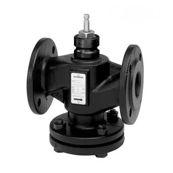
VVF21 Siemens
Control valve flanged
production of discontinued
 calculation and selection
 Technical description


technical
specifications
price
| DN mm |
Kvs m³/h |
L mm |
h mm |
compatible with actuator |
price |
|---|---|---|---|---|---|
| 25 | 1.90 2.50 3.00 4.00 5.00 6.30 7.50 10,0 |
150 | 20 | 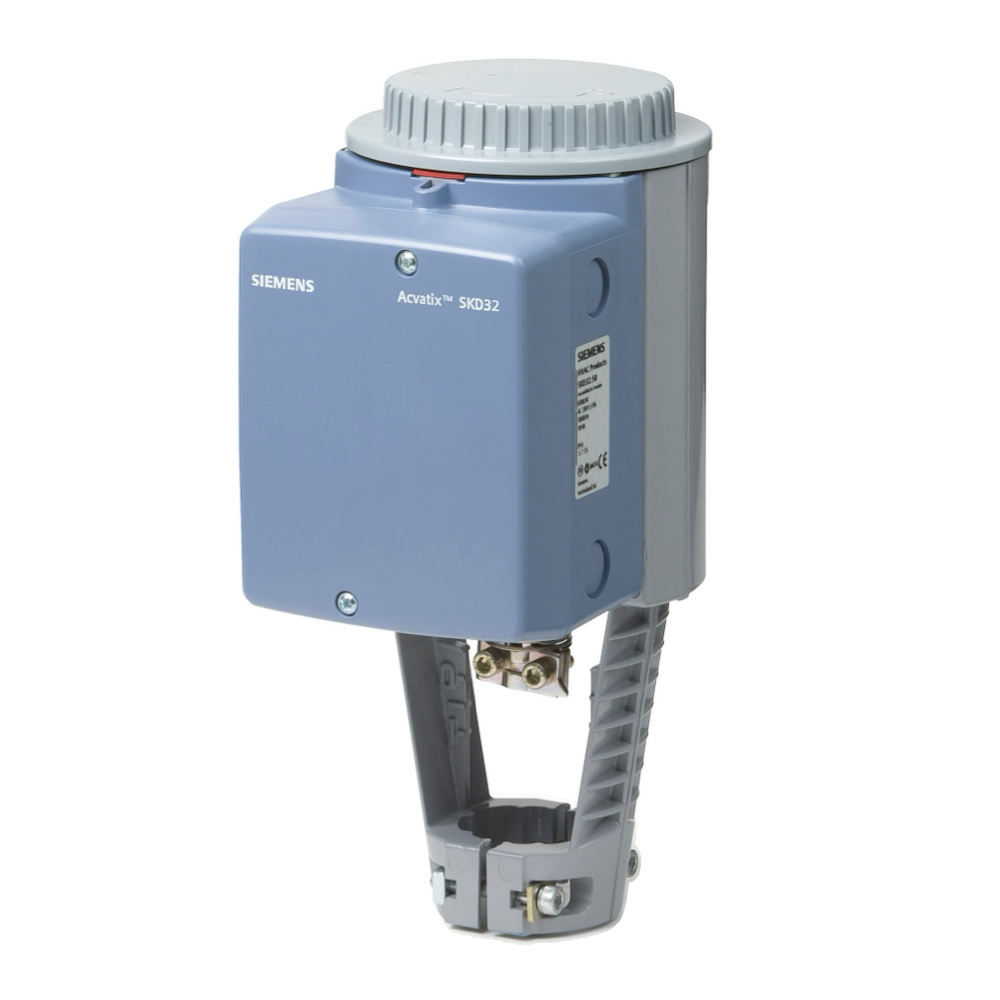
SKD32
Siemens : dPmax = 3.0 bar 
SKD60
Siemens : dPmax = 3.0 bar 
SKD82
Siemens : dPmax = 3.0 bar 
SKB32
Siemens : dPmax = 3.0 bar 
SKB60
Siemens : dPmax = 3.0 bar 
SKB82
Siemens : dPmax = 3.0 bar |
production of discontinued |
| 40 | 12 16 19 25 |
180 | 20 |
SKD32
Siemens : dPmax = 3.0 bar
SKD60
Siemens : dPmax = 3.0 bar
SKD82
Siemens : dPmax = 3.0 bar
SKB32
Siemens : dPmax = 3.0 bar
SKB60
Siemens : dPmax = 3.0 bar
SKB82
Siemens : dPmax = 3.0 bar |
production of discontinued |
| 50 | 31 40 |
200 | 20 |
SKD32
Siemens : dPmax = 3.0 bar
SKD60
Siemens : dPmax = 3.0 bar
SKD82
Siemens : dPmax = 3.0 bar
SKB32
Siemens : dPmax = 3.0 bar
SKB60
Siemens : dPmax = 3.0 bar
SKB82
Siemens : dPmax = 3.0 bar |
production of discontinued |
| 65 | 49 63 |
240 | 20 |
SKD32
Siemens : dPmax = 2.8 bar
SKD60
Siemens : dPmax = 2.8 bar
SKD82
Siemens : dPmax = 2.8 bar
SKB32
Siemens : dPmax = 3.0 bar
SKB60
Siemens : dPmax = 3.0 bar
SKB82
Siemens : dPmax = 3.0 bar |
production of discontinued |
| 80 | 78 100 |
260 | 20 |
SKD32
Siemens : dPmax = 1.8 bar
SKD60
Siemens : dPmax = 1.8 bar
SKD82
Siemens : dPmax = 1.8 bar
SKB32
Siemens : dPmax = 3.0 bar
SKB60
Siemens : dPmax = 3.0 bar
SKB82
Siemens : dPmax = 3.0 bar |
production of discontinued |
| 100 | 124 160 |
300 | 40 | production of discontinued |
DN - nominal diameter, mm.
L - length along the pipeline axis, mm.
h - valve stem travel, mm.
dP - permissible pressure drop across the valve (for water), bar.
Kvs - flow capacity, corresponds to the water flow rate in m³/h, at which the pressure drop across the valve will be 1 bar.
question : comment : feedback
 Catalog of
 control valves
Belimo
Belimo
Danfoss
Danfoss
Danfoss
Danfoss
LDM
LDM
LDM
Honeywell - Resideo
Honeywell - Resideo
Honeywell - Resideo
IMI Hydronic
IMI Hydronic
IMI Hydronic
IMI Hydronic
ESBE
ESBE
ESBE
КПСР Групп
КПСР Групп
КПСР Групп
Clorius
Honeywell - Resideo
ESBE
ESBE
ESBE
Clorius
Clorius
Siemens
Siemens
Siemens
Siemens
Siemens

