Please do not block ads on our site. Clicks on ads help us exist, grow and become more useful for you!
Installation of a Circulation Pump
Installation of circulation pump in heating and hot water supply systems should be carried out in accordance with the project of these systems and the manufacturer's installation instructions. Below are some general recommendations regarding the installation of wet rotor pumps:
Mounting position
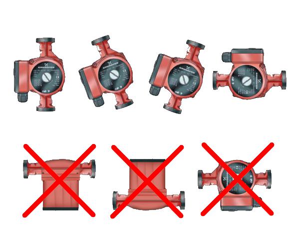
- The shaft axis should be horizontal. Otherwise, the pump will overheat and the protection will be tripped.
- Pumps with wet rotor do not require support frames and foundations, unless otherwise specified in the installation instructions.
- The arrow on the pump body should coincide with the technological direction of water flow at the installation location.
- The circulation pump can be installed on both the supply and return pipelines of the heating system, although it is recommended to install the circulation pump where the temperature of the pumped water is minimal.
- Thermal insulation is applied only to the pump body. Thermal insulation of the motor is not allowed.
Pipeline layout
- The diameter of the inlet and outlet pipelines, as well as the nominal diameters of the fittings installed on them, are determined by calculation and usually exceed the nominal diameter of the pump flange by 1-2 types. Therefore, the connection of pipelines to the pump is made through transitions.
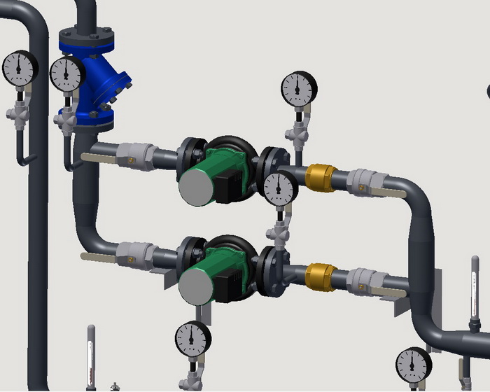
- A strainer should be installed before the circulation pump, in the direction of water flow, as well as shut-off valves, anti-vibration inserts, and pressure gauges before and after it. Low-power pumps can be installed without anti-vibration inserts.
- If two or more pumps are installed in parallel on the discharge flange of each of them, a check valve should be installed. In heating systems, the installation of a backup circulation pump is mandatory.
- The pump body should not be subjected to twisting, stretching, bending, or compression loads from connected pipelines. Connecting pipelines should be coaxial.
- When threaded pipelines are used, the pump should be installed using adjustable wrenches.
- When flange mounting the circulation pump, the counter flanges should be parallel, gaskets made of material that corresponds to the properties of the working environment should be installed between the flanges, and washers should be placed under the clamping bolts and nuts.
- If air can accumulate in the pump's layout, automatic air vents should be installed in possible places of accumulation.
- A drain valve should be installed at the lowest point of the pipeline section disconnected from the pump.
- Before installing the circulation pump, it is necessary to flush the inlet pipelines.
Electrical connection
- The pump must be connected to the electrical network through an automation panel with basic protection and control.
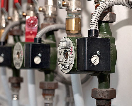
- The pump's installation position should prevent water from entering the terminal box. It is not recommended to install the terminal box below the motor.
- Pumps that are resistant to blocking currents and pumps with built-in winding protection against overheating do not require additional protection.
- The pump housing must be grounded.
Threaded joint packing sequence
1. Take a bundle of flax thread with enough threads so that when twisted, its diameter is approximately equal to the depth of the thread on the assembled element. The length of the bundle should provide 1.5-2 times more turns than the number of thread turns.
2. After about 50-70 mm from the beginning of the bundle, twist it slightly, place it in the first thread turn, and holding it by hand, tightly wind the long branch of the bundle clockwise, laying it in each thread turn.
3. When the end of the thread is reached, continue winding with a second layer, moving the turns to the beginning of the thread. The length of the second layer winding should be approximately two-thirds the length of the thread.
4. Wind the remaining end of the bundle (50-70mm) in a similar manner clockwise, laying it from the end of the thread to its beginning.
5. Apply a layer of sealant to the winding surface.
6. Screw the connecting elements by hand. With proper winding, the assembled element should be wound 1.5-2 turns.
7. Continue winding the element with a wrench or torque wrench. If the assembled element needs to be in a certain position, finish winding it in the required position.
When properly wound, the force during winding should not exceed the tightening torque specified below:
| DN15 |
DN20 |
DN25 |
DN32 |
DN40 |
DN50 |
DN65 |
DN80 |
DN100 |
| 70 Nm |
95 Nm |
120 Nm |
150 Nm |
190 Nm |
230 Nm |
280 Nm |
350 Nm |
400 Nm |
Tightening torques for hexagon nuts of flange connections
| DN |
Nut/Bolt |
Torque, Nm |
| 15 - 32 |
М 10 |
15 - 30 |
| 40 - 65 |
М 12 |
35 - 50 |
| 80 - 100 |
М 16 |
75 - 100 |
| 125 - 150 |
М 16 |
80 - 120 |
| 200 |
М 20 |
150 - 200 |
| 250 - 400 |
М 24 |
340 - 410 |
| 500 |
М 27 |
340 - 410 |


 Heating and domestic hot water systems for dwellings
question : comment : feedback
987
 Catalog of
 circulation pumps
DAB
DAB
DAB
DAB
IMP Pumps
IMP Pumps
IMP Pumps
IMP Pumps
IMP Pumps
Wilo
Wilo
Wilo
Wilo
Calpeda
Calpeda
Calpeda
Calpeda
Calpeda
Grundfos
Wilo
Wilo
Wilo
Wilo
Wilo
Calpeda
Calpeda
Grundfos
Grundfos
Grundfos
Grundfos
Grundfos
DAB
DAB
Smedegaard
Smedegaard
Smedegaard
Lowara
Lowara
Lowara
Lowara
Lowara
IMP Pumps

