Please do not block ads on our site. Clicks on ads help us exist, grow and become more useful for you!
Installation of Centrifugal Pump
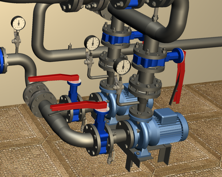
Installation of a centrifugal pump should be carried out in accordance with the manufacturer's instructions and the project design. Below are general recommendations for installing monoblock pumps with air-cooled electric motors.
Installation
- Installation of a monoblock pump is only allowed with a horizontal shaft position.
- Pumps up to 5-10 kW are installed on a steel frame, while larger pumps are installed on a foundation. The weight of the concrete foundation should be at least twice the weight of the pump with the electric motor. The length and width of the concrete foundation should exceed the dimensions of the frame by 100 mm on all sides. If necessary, vibration and noise isolation for powerful pumps is achieved by a vibration-isolated foundation.
- The pump housing is attached to the frame or foundation with bolts through holes in the support feet.
- For air cooling of the electric motor, a free space of at least 0.5 m should be left to the nearest enclosing structure.
- If thermal insulation is performed, only the pump housing and connecting pipes should be insulated. Thermal insulation of the motor is not allowed.
- Before installation, make sure that the pump shaft moves freely.
- Before installing the pump in the system, flush the pipelines from sediment, slag, and other debris.
Connection to the Pipeline
- The working fluid enters through the axial and exits through the radial nozzle of the pump.
- The diameter of the supply and discharge pipelines is chosen according to the calculation and, as a rule, is greater than the diameter of the pump nozzles by 1-2 nominal sizes.
- The pump housing should not withstand torsion, tension, bending, or compression loads from the connected pipelines.
- To perform maintenance, shut-off valves should be installed on the pipeline before and after the pump. The disconnected section should be equipped with a drain valve.
- To protect the pump from damage by solid particles, a mesh filter should be installed in front of it.
- To avoid transferring vibration to the connected pipelines, anti-vibration inserts should be installed on the pump risers.
- In multi-pump installations with parallel connected pumps, a check valve should be installed on the pressure nozzle of each pump.
- The control flanges of the connected pipelines should be parallel to the pump flanges, and gaskets corresponding to the parameters of the pumped liquid should be installed between the flanges.
- To monitor the pump operation before and after it, pressure gauges should be installed.
Requirements for the premises
- The temperature in the room where the pump is installed should not drop below zero. When installing pumps that are allowed to be installed outside, the manufacturer's recommendations for protection against precipitation and direct sunlight should be followed.
- Pumps with air-cooled motors should be installed in well-ventilated rooms. The ventilation system should work continuously throughout the pump's operation and provide stable heat dissipation from the cooled motor.
- The temperature in the room should not exceed 40°C, otherwise the motor cooling will be ineffective.
Electrics
- The pump housing must be grounded.
- The mounting position should prevent drops from falling on the pump's junction box.
- The pump should not be installed with the motor or junction box facing downwards.
- Pumps that are resistant to blocking currents and pumps with built-in winding protection against overheating do not require additional motor protection.
Threaded connection assembly sequence
1. Take a bundle of flax thread with enough threads to make the twisted diameter approximately equal to the depth of the threaded hole in the installed part. The length of the bundle should provide 1.5-2 times more turns than the number of thread turns.
2. Moving approximately 50-70 mm away from the beginning of the bundle, slightly twist it, place it in the first thread turn, and holding it with your hand, tightly wind a long branch of the bundle clockwise, laying it in each thread turn.
3. When reaching the end of the thread, continue winding with the second layer, moving the turns to the beginning of the thread. The length of the second winding layer should be approximately 2/3 of the thread length.
4. Wind the remaining end of the thread (50-70 mm) clockwise, laying it from the end of the thread to its beginning.
5. Apply a layer of sealant to the wound thread.
6. Turn the part by hand. With the correct winding, the installed part should turn 1.5-2 turns.
7. Continue to tighten the part with a wrench or torque wrench. If the installed part needs to be in a specific position, finish tightening it in the required position.
During tightening, the force should not exceed the tightening torque specified below:
| DN15 |
DN20 |
DN25 |
DN32 |
DN40 |
DN50 |
DN65 |
DN80 |
DN100 |
| 70 Nm |
95 Nm |
120 Nm |
150 Nm |
190 Nm |
230 Nm |
280 Nm |
350 Nm |
400 Nm |
Flange joint bolt tightening torques
| DN |
Nut/Bolt |
Torque, Nm |
| 15 - 32 |
М 10 |
15 - 30 |
| 40 - 65 |
М 12 |
35 - 50 |
| 80 - 100 |
М 16 |
75 - 100 |
| 125 - 150 |
М 16 |
80 - 120 |
| 200 |
М 20 |
150 - 200 |
| 250 - 400 |
М 24 |
340 - 410 |
| 500 |
М 27 |
340 - 410 |


 Heating and domestic hot water systems for dwellings
question : comment : feedback
306
 Catalog of
